
|
|
Forum Index : Electronics : Mab1's wiseguy inverter build - transformer options
| Page 1 of 8 |
|||||
| Author | Message | ||||
| mab1 Senior Member Joined: 10/02/2015 Location: United KingdomPosts: 282 |
Probably getting ahead of myself here seeing as the boards are still in customs (i guess)  But as I've been planning an inverter build for some time, i already have some transformers to choose from:- Option 1. 3kva aerosharp 230v / 250v. 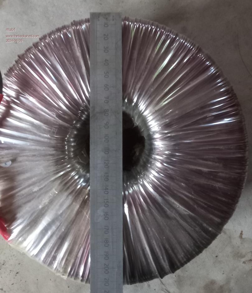 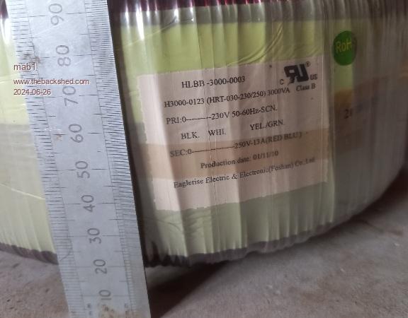 Of course the 250v winding is on the outside  - i could add a few turns to the 230v winding and run them parallel, but that leaves little room for the primary. - i could add a few turns to the 230v winding and run them parallel, but that leaves little room for the primary.Option 2. 20A 240v variac core 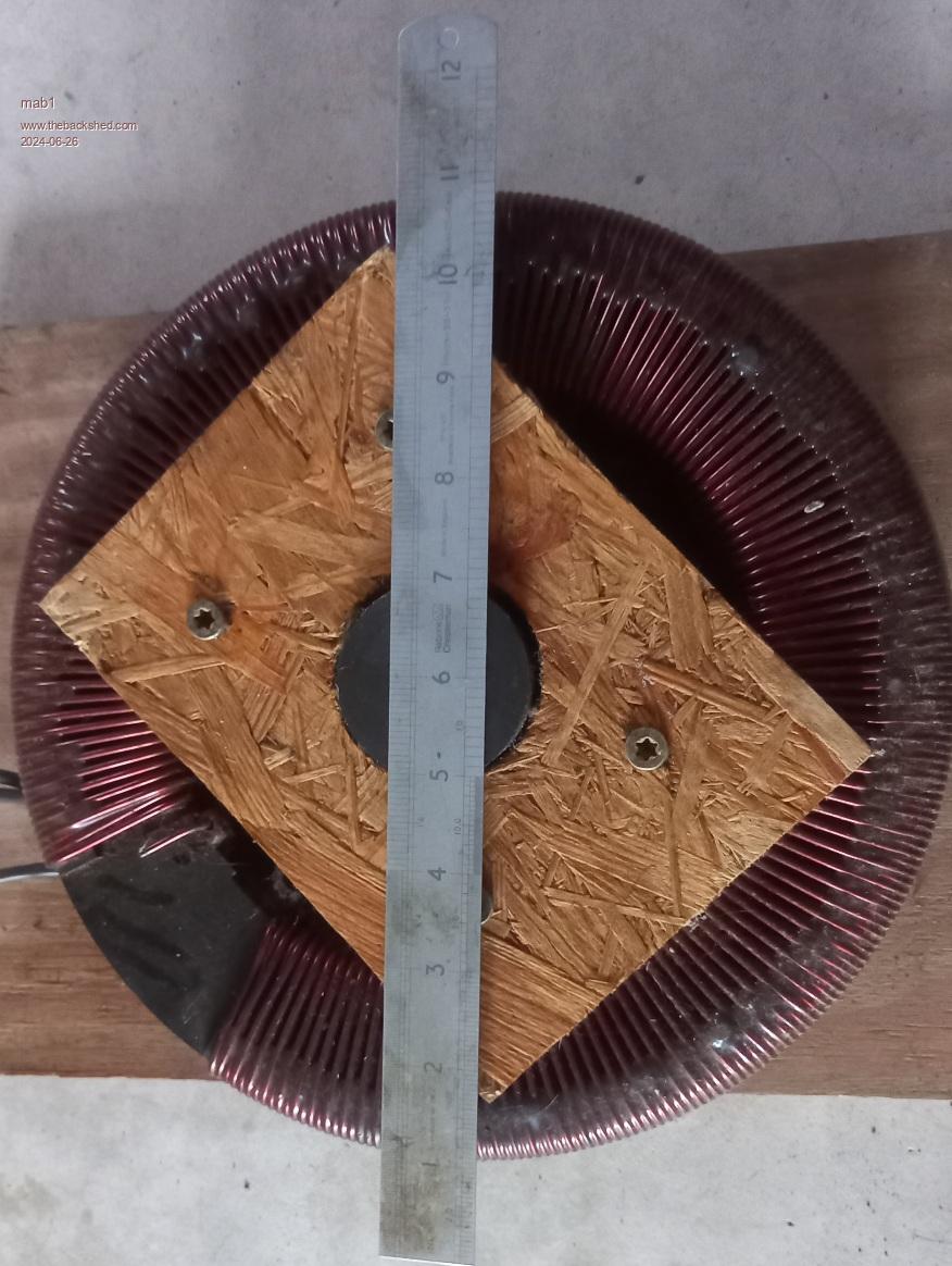  I actually got this cheap as it was just the core as is, without the 'variac' bits, and was vaguely planning on rebuilding it into a variac - but realistically if i really want a 20A variac (i already have 4, 5 and 10A units), given my limited engineering skills, I'd be better off just buying a working one. It has the bonus of already having a 240v winding, and a HUGE centre hole for winding the primary - but I'm not sure what power it could be as a regular transformer. Option 3. (2 off) 3.3kva santerno inverter transformers 180v / 230v  I've already removed the 230v winding from one: 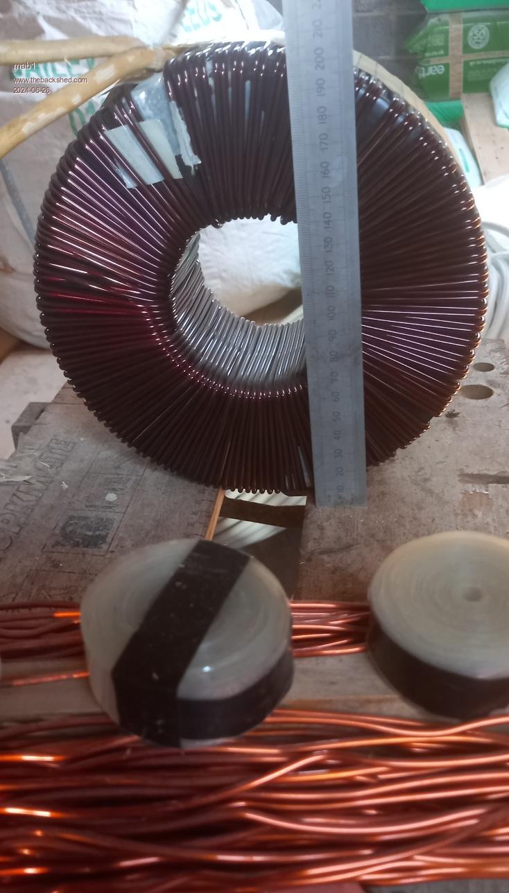 The original plan was to unwind, put the cores together and make a massuve 6kva unit like clockmanfr - but that's a LOT of unwinding/winding!  Keepis gave me the idea of keeping the inner windings and stacking, but 2x180v seems a little ott to me - although i could unwind part of each i suppose? |
||||
| mab1 Senior Member Joined: 10/02/2015 Location: United KingdomPosts: 282 |
Thought I'd better post in case i 'lost' all my typing. So the plan is to build a inverter for the house, and a 48v pack to go with it to upgrade from the existing 24v powerjack inverter - seem like now's the time to go 48v:- when i use the ASHP to heat the water it can pull 3.6kw, and the powerjack is struggling at that point (lights getting dimmer). I also plan to build the variac inverter, but as that's for experimenting, etc i probably can use the 2nd or even 3rd best transformer option for that (2nd going for some sort of backup inverter). So the question:- which transformer option would you go with  (or can you suggest a better option?)? (or can you suggest a better option?)?Just a size comarison: variac and 3kva aerosharp 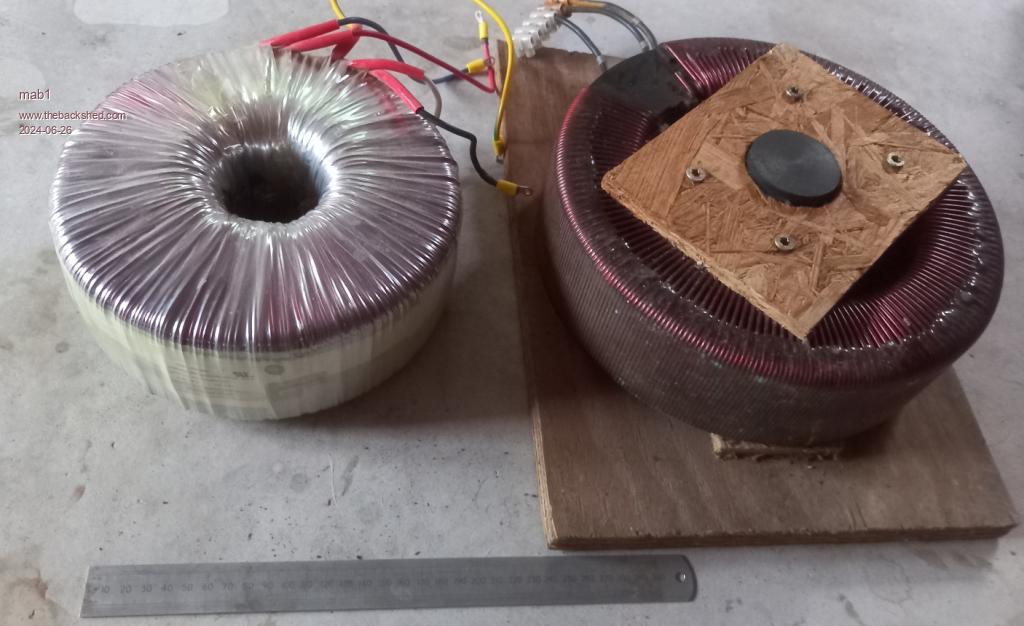 Edited 2024-06-26 06:41 by mab1 |
||||
| wiseguy Guru Joined: 21/06/2018 Location: AustraliaPosts: 1296 |
I would be very tempted to use the 2 x Santerno toroids, removing ~ 40T from each and then stacking them and putting the windings in Series. Primary wound through both at once and only ~ 12 turns needed. This is just a rough guesstimate but should be good for at least 5kVA continuous? Second choice would be to try the Variac, need to check volts per turn but primary will probably end up with probably 22 - 26 Turns, - a bit more winding. Transformers are not my strongest point but maybe someone else can confirm my suggestion if you decide to go either way? If at first you dont succeed, I suggest you avoid sky diving.... Cheers Mike |
||||
| mab1 Senior Member Joined: 10/02/2015 Location: United KingdomPosts: 282 |
That sort of chimes with my own thought - The variac is tempting 'cos i only have to wind a primary on it, whereas the Santerno double would involve a lot of unwinding first. But it'll have a much larger cross section of iron than the variac, which makes me think it'll be more 'powerful' - and yet the variac would seem to accommodate a substantial amount of copper so it ought to be pretty good.laying it out on here helps to organise my thoughts, but i suspect i will go with the santerno, but if i'm still working on it when the boards are ready i might end up winding a primary on the variac as a quick transformer. When you say unwind 40T from the santerno's i assume you mean unwind about 40 volts worth of turns? (though it may well be about 40T) so with the two in series it would be 280v nominal, giving me a low gauss density and low idle losses at 230v. |
||||
| KeepIS Guru Joined: 13/10/2014 Location: AustraliaPosts: 2177 |
280vac sec will bring you into the same voltage area as my 3 toroid stack. I was going to suggest you calculate the cross section of two stacked compared to the Variac, looks like you have done that, so the stacked option is the way to go. It would be interesting to hear how that Variac goes as a test unit, or as an electronic Variac that wiseguy and Poida designed. NANO:Inverter V 8.2ks - Linux AvrDude GUI script V4.1 |
||||
| Godoh Guru Joined: 26/09/2020 Location: AustraliaPosts: 664 |
One way around the massive power draw from the hot water system is to put a smaller element in the tank. You could easily replace the 3.6kw element with a 2.4 kw or even a 1.2 kw element. Depends on just how fast you need the hot water to be heated up. Pete |
||||
| wiseguy Guru Joined: 21/06/2018 Location: AustraliaPosts: 1296 |
Yes the 40 turns was a guess it looks like the transformer has ~ 135T - hard to count from picture. When KeepIS stacked 3 cores that were nominally 90V each = 270V so with a 240V output he is running a bit lower flux than the original design but he still has great surge power. I figured that if you get the two transformers in the same ball park 260 - 270V when added together should give similar results. I agree that with the extra iron and surface area should all help with performance and maybe less overall heat than the one lump. I have also been thinking about the 3kW Aerosharp, it appears to be a similar production to two that I have, that is 195T for 230V and 212T for 250V. If you expose the outer winding and count back 9 turns from the 250V winding you are left with 203turns. If you unwind one turn from the remaining 9T winding you have 8T which when added to the 195 gives you another 203T winding. Apply some thinking before deciding where to place the initial cut as when done well it will give reasonable length stubs for the 2 ends that need to be brought out. The 1T extra you unwound gives some isolation on that same layer as the windings may have nearly full mains between them depending on how you phase them but it gives an ultra low impedance mains output and bit lower Flux for a 230 - 235V output. This is all theory and supposition as I have not unwound one to check yet. Edit: I dug out the 3kW Aerosharp toroid and had a closer look - it is a "scatter wound" affair, whilst it sounded simple counting back 9 turns, it looks a bit of a problem in the flesh. undoing 9 turns should be relatively simple, winding back on 8 turns but using a mylar separator (20mm wide?) might work ok. Just adding 17T in a similar fashion as an overwind is starting to look more attractive... I have some 10mm cable that is only around 7mm diameter and it should easily carry 35A continuous, I am thinking of winding two lengths at once for an easy 70A primary or ~ 3-3.5kW continuous. My modelling says it should easily fit. Edit: I started this post and then got back to it later - meanwhile after I posted I saw 2 more posts had appeared..... Edited 2024-06-27 18:46 by wiseguy If at first you dont succeed, I suggest you avoid sky diving.... Cheers Mike |
||||
| mab1 Senior Member Joined: 10/02/2015 Location: United KingdomPosts: 282 |
Thanks for that! I was hoping to do a bit of unwinding work today but have run out of time (again)  KeepIS: i hadn't actually measured the core area, just judged by eye, but i did manage to measure the core sections today as best i could though:- 42 x 60 mm variac = 2520mm2 74 x 52 mm each santerno = 3848mm2 Can't really tell with the aerosharp as it's still intact. So the double stack santerno should be 3x the iron area of the variac. WG: adding 17 turns to the aerosharp sounds like the easiest option for that transformer- i have the wire and mylar i unwound from the 1st santerno 230v winding to try it, and i have lots of 10mm2 16mm2 and 25mm2 houshold wire here, though the hole in the centre looks very small to get 2x 10mm2 through to me. But it does sound like the santerno double stack should be the 1st choice for the house inverter - though just the thought of all that unwinding makes my elbows hurt Pete: i probably didn't explain the water heater properly:- the tank has an immersion, but i can also use the air source heat pump ( ASHP - that heats the house via underfloor heating) to heat the water. If energy is scarce, the heat pump can put a lot more heat into the tank for a given amount of electrical energy:- when the water's cold it can put 10kw of heat into the tank for 2kw of electricity. As the tank heats up the HP has to work harder and the performance drops, so when the tank gets to 55C (the limit of the HP) it's running flat out at 3.6kW, but still puts 6kW of heat into the tank. |
||||
| Godoh Guru Joined: 26/09/2020 Location: AustraliaPosts: 664 |
Hi Mab, the water heater setup sounds pretty good. The last transformer I made had a fairly small hole left in the middle after the secondary went on. I used flat fibreglass insulated copper bar that is used for rotor winding. I only just managed to get the required turns in but it works great, is very quiet and dumps heat well as there is no PVC insulation to hold the heat in. I bought it from a motor rewinding shop. I have enough left to change the primary on my other ( powerjack transformer) inverter. It has too many turns and seems to over saturate. So I plan to rewind it totally too. I have 2.8mm winding wire for the primary and the flat bar for the secondary. Have fun hope it works out well Pete |
||||
| KeepIS Guru Joined: 13/10/2014 Location: AustraliaPosts: 2177 |
FYI, I have a lower rated aerosharp in the test inverter. I cut off the secondary, left the copper tape shield, and wound 26 turns of plastic covered copper cable and it outputs 240v at 75% PWM and can start over 400A of DC input surge load. That center hole got a lot bigger once the secondary was removed. Would get you up an running easily to start with. Build the bigger dual unit later. NANO:Inverter V 8.2ks - Linux AvrDude GUI script V4.1 |
||||
| mab1 Senior Member Joined: 10/02/2015 Location: United KingdomPosts: 282 |
Hmm. I do wonder then if i should do the aerosharp as an option if i don't need the power of the dual unit (lower standing loss)? with my existing consumption, even with the ASHP, it would probably cope. But at some point i will be getting an EV and more solar and more battery, so i think the dual unit would be betterwhen i get to that point - i guess it boils down to how far I've progessed the dual unit by the time i need a tx I did stack them to compare sizes directly- the two 3.3kva santernos on top and the aerosharp 3.0kva on the bottom - curiously the aerosharp looks bigger - but maybe that's the earth screen layer bulking it up 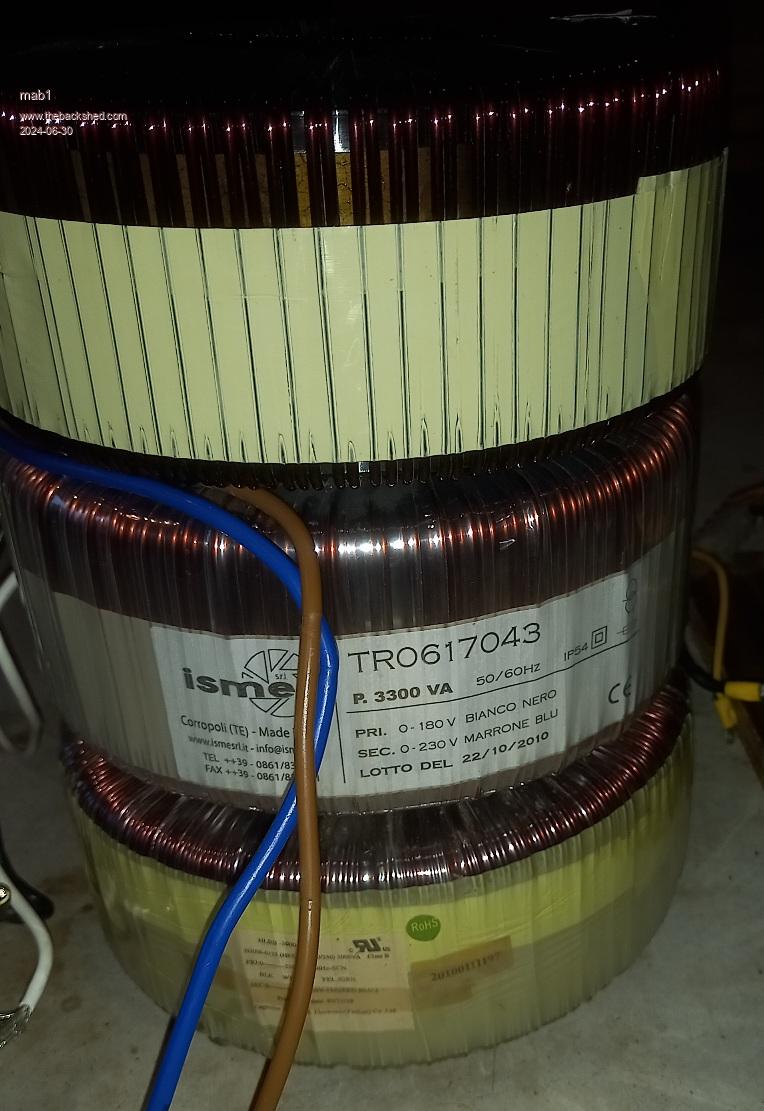 I suspect the cores are very similar sizes - prompting the (mad) thought that i could do a triple stack 9kva!! but if your 3x2kva does your workshop and house, i definitely don't need 9kva - and i probably wouldn't be able to move it without an engine hoist.So, back to sanity: I counted 155turns for the 180v winding (took three counts to get two the same) So that's 1.163 v/t So 140v nominal (but actually to run at 230/2v) = 121 (120.55) turns. On second thoughts, maybe i need to do some measurements to see what the idle current/power will be, so connecting the tx to a variac and watt meter:- For the 180v winding on the tx I've started unwinding: Volts amps watts 116 0.04 5.0 140 0.05 7.2 160 0.06 9.5 180 0.08 12.8 For the 230v winding on the intact tx:- Volts amps watts 180 0.03 6.6 200 0.03 8.1 220 0.04 9.9 230 0.05 11.0 240 0.05 12.2 Ok I've confused myself now but i think if i wind 121 turns on each and run at 115v each, thats 82% nominal voltage, or equivalent to running 148v on the 180v winding or 188v on the 230v winding Interpolating the tables above that would be 8.3w per core from the upper table or 7.4w per core from the lower table. Not sure why don't agree better, but i guess they're plausible figures Edited 2024-06-30 07:53 by mab1 |
||||
| KeepIS Guru Joined: 13/10/2014 Location: AustraliaPosts: 2177 |
FYI in my real world tests, the idling current was similar for 3 stacked toroids as it was for one. It comes down to winding setup. My testing on the 3 Stack Toriod with a Variac. 26.8v = 225v @ 13.6 watts 27.3v = 230v @ 14.5 watts 28.4v = 240v @ 16.0 watts 29.8v = 250v @ 18.0 watts 31.0v = 260v @ 19.0 watts 32.0v = 270v @ 22.7 watts 33.3v = 280v @ 26.0 watts Bare transformer tested with a Variac 14 turn primary at @ 27.3VAC = 230VAC out @ 15 Watts. NANO:Inverter V 8.2ks - Linux AvrDude GUI script V4.1 |
||||
| mab1 Senior Member Joined: 10/02/2015 Location: United KingdomPosts: 282 |
Hmmm.. thats interesting. I guess I'll just have to wind it and see - leave a few extra turns on just in case maybe. I haven't started on the unwinding work yet though - been too larthargic after work to make a start but i have started populating the nano pcb with resistors, and placed an order for fets, transistors and some other parts with lcsc  |
||||
| wiseguy Guru Joined: 21/06/2018 Location: AustraliaPosts: 1296 |
I have looked at that statement for a couple of days and I probably am having a mental block/senior moment but I am having trouble with it. So could you please either clarify what it means or say it differently so hopefully I can get it. In all the testing I have done if I drive a core to a particular flux density even on the idle it takes energy = X. If I stack 2 cores and drive them both to the same flux density it now takes 2X. If I rearrange your statement to say it slightly differently; "In my real world tests, the idling currents per toroid was similar in 3 stacked toroids as it was for one. It comes down to winding setup" Hopefully by rearranging your statement you can understand my confusion or misread of what you are saying. How do you measure the winding power is it RMS volts x RMS current (which will not tell the truth)? Edited 2024-07-03 11:45 by wiseguy If at first you dont succeed, I suggest you avoid sky diving.... Cheers Mike |
||||
| Murphy's friend Guru Joined: 04/10/2019 Location: AustraliaPosts: 678 |
I believe KeepIS has a very unusual transformer stack where each transformer only has 1/3 of the required secondary turns. These were then connected in series. Here at my place I only ever stacked two *blank* cores, where the secondary is wound over both cores as one. With this arrangement the idling current doubles from what it would be if only one core was wound. |
||||
| wiseguy Guru Joined: 21/06/2018 Location: AustraliaPosts: 1296 |
If I understand this properly, I believe KeepIS had 3 transformers that were each 90V - 240V. He unwound the 240V windings and was left with 3 x 90V windings. To get 90V he needs the same flux as generated the 240V. So when the 3 windings are added in series to get hypothetically 270V they must all have the same as the original flux x 3. I know he actually was after 240V so the transformers are not exactly the flux required for 90v instead ~80V are around 90% of the initial flux for 90V ? Despite the fact the 3 transformers are stacked and have a common primary and the 3 output windings are in series there are certain fundamentals that don't change ? Can we extend the argument that if we get enough transformers stacked we can reduce the flux to almost zero but still have all the series secondaries generating our desired output ? Thanks for trying to help but I sill don't follow or understand the original statement. BTW your closing sentence is essentially what I am saying ie "Here at my place I only ever stacked two *blank* cores, where the secondary is wound over both cores as one. With this arrangement the idling current doubles from what it would be if only one core was wound." That was why I expected 3 x the one toroid because essentially he is doing the same thing in my mind that you are. Edited 2024-07-03 23:07 by wiseguy If at first you dont succeed, I suggest you avoid sky diving.... Cheers Mike |
||||
| analog8484 Senior Member Joined: 11/11/2021 Location: United StatesPosts: 203 |
It seems there is different usage/meaning of "primary" and "secondary" windings in different posts. I've seen this create confusion elsewhere. Perhaps it would be better to use "LV" and "HV" windings? |
||||
| Murphy's friend Guru Joined: 04/10/2019 Location: AustraliaPosts: 678 |
To me it's quite simple: primary is where the power enters, secondary is where the power leaves a transformer. Why confuse it with acronyms? |
||||
| mab1 Senior Member Joined: 10/02/2015 Location: United KingdomPosts: 282 |
I'm with MF on this: convention AFAIK defines the primary as the input winding, but i agree it can get confusing, particularly when re-purposing transformers where a particular winding might have been the primary in the original context but has now become the secondary. When using torroidal transformers there's an additional ambiguity as the manufacturers might(?) Define the primary as the 1st (inner) winding: if you look at the pic of the 3 stacked transformers above the santerno defines the 180v (power in)winding as the primary, yet the aerosharp defines the 230v (power out) as the primary: - they're both the inner windings. But to me the primary is the power input winding, and any other definition would confuse me  |
||||
| analog8484 Senior Member Joined: 11/11/2021 Location: United StatesPosts: 203 |
deleted Edited 2024-07-06 02:27 by analog8484 |
||||
| Page 1 of 8 |
|||||
| The Back Shed's forum code is written, and hosted, in Australia. | © JAQ Software 2026 |
