Notice. New forum software under development. It's going to miss a few functions and look a bit ugly for a while, but I'm working on it full time now as the old forum was too unstable. Couple days, all good. If you notice any issues, please contact me.
poida Guru Joined: 02/02/2017 Location: AustraliaPosts: 1476
Posted: 03:48am 09 Jun 2024
Copy link to clipboard
Print this post
I found out how Victron mppt controllers work and it's not pretty when there is more than enough power on the input.
Let's say the controller is the 75/15 model. This means it's max output current is 15A My battery is 12V Lithium and it's at about 13.4V now 15A into 13.4V is about 200W This is what should be the max that the battery will be charge at. And close to the max of what the solar input will pull.
I want to charge the battery prior to a trip and Melbourne is not cooperating (i.e. deep cloud + rain)
I first put a 30V @5A supply on the solar input. The controller does it's max power scan and chooses 19V @ 5A to operate at. (only 100W, when it could run at 30V at 5A or 150W)
OK, this is telling, the mpp scan seems a bit crap but what's new, it's Victron.
I then put a 2kW flatpak supply on it. The controller will act like a dc-dc converter and just take what it needs and everything will be fine. right? RIGHT? The flatpak has a 40A max output, at about 55V, max output limited to 2000W I saw, after connecting this to the mppt solar inputs, 40A on the input wires and they were getting quite warm. The 15A mppt was putting something like 15A into the battery, but only for a second or two. Then it put nothing into the battery while it did a scan. During the scan, the input is shorted, internally. It was something like 1 second 15A out, 5 seconds shorted inputs.
So the Victron 75/15 mppt shunts any input greater than it's rated output. This is not how a dc-dc step down converter operates. And it's not how my mppt design works either. My design works as a dc-dc converter. Any excess input power (e.g. input is 3Kw, output is set to 1.5kW, so 1.5W is drawn from input) is not used, it lets the input float up to whatever the input wants to source.
I did not blow the 75/15 mppt. I found another supply that I can drive at constant current at near 200W and charge the battery at max power without shunting 1800W if the flatpak was used.
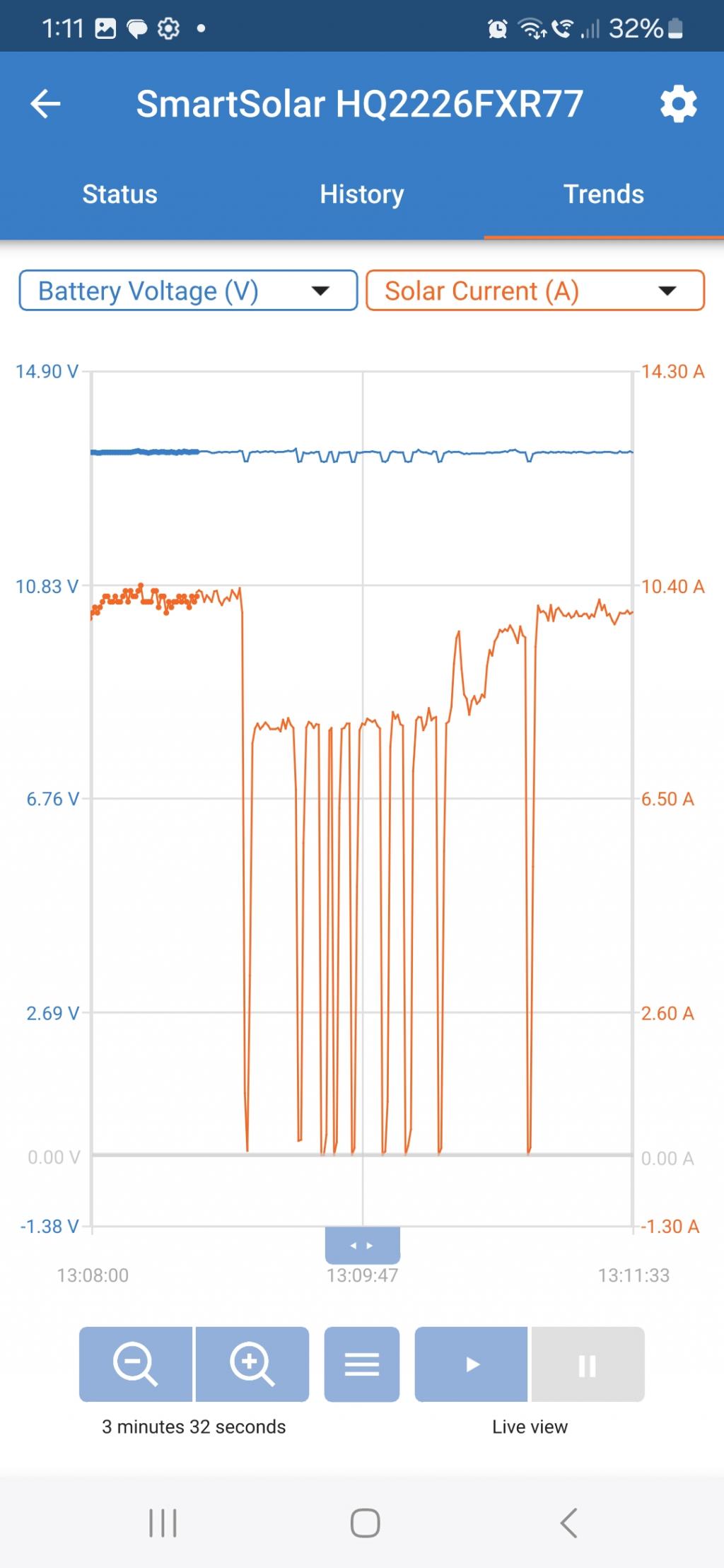
Victron provide an app for the phone. It shows input and output volts, Amps etc.
the first screenshot shows input current. it was at 12A, which was maxing out the 200W output This was the PS constant current output limit, 12A I then increased the CC limit to 20A and we see the mppt scanning seeing there is too much, shunting it (and showing what IT thinks is input current when shunted, but it's wrong. It's measured AFTER the shunt, on the battery output) Then I reduce PS current to 12A and the mppt scans, sees output is 15A or less and gets back to work.
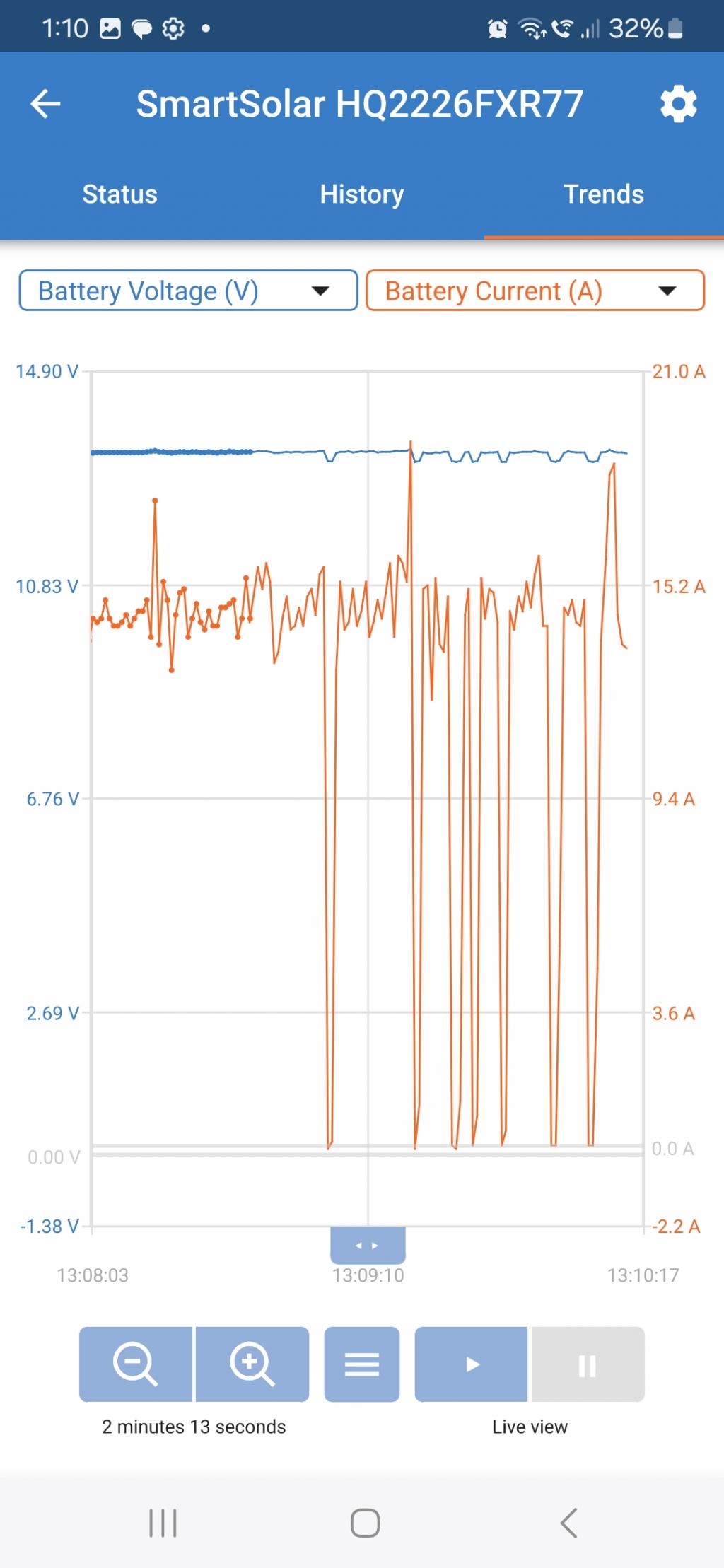
The second image shows output (to battery) current (the device has a max of 15A) during the above tests.
The power supply shows about 20A output when the CC limit is set to 20A and this was when the mppt said it was pulling 8A (in first image)
what a piece of crap.wronger than a phone book full of wrong phone numbers
Godoh Guru Joined: 26/09/2020 Location: AustraliaPosts: 664
Posted: 04:06am 09 Jun 2024
Copy link to clipboard
Print this post
Wow Poida, that does look like a crappy system. It seems to work like a shunt regulator rather than just reducing the voltage when throttling is needed. Seems more like a motorcycle regulator than an expensive MPPT regulator. Thanks for taking the time to put up the graphs and test results. I had already decided long ago that that brand were not worth having as they were non-repairable without a huge amount of trouble getting them apart. There are times that I would love to just have one big regulator, but it does not seem feasible to have one capable of working on 10kw of panels. I do find that the VRLA batteries I have will not take much more than around 2kw of charger anyway. But when the car is on the charger my panels can be putting out 5 or more KW. thanks again Pete
rustyrotors Newbie Joined: 07/01/2023 Location: United StatesPosts: 36
Posted: 04:22pm 12 Jun 2024
Copy link to clipboard
Print this post
i was curious i tried it with my victron 100/50 and a 4S lipo, but i only have a 30V, 10A, 300W power supply. i set the victron for 16.5V bulk 5A output, and i didnt notice any shunting behavior at the input, no current or voltage spikes on the logger or oscope. it seemed to work pretty well, with 30V input at 2.5A. i decrease the CC limit on the power supply to 1A and it finds 30V input like it should. i also tried victron set for max current 50A, and it maxed out the power supply at 30V, 10A like it should
one interesting behavior was if i added capacitance to the input (i actually wired my spare inverter powered off with 40000uF) it no longer finds MPPT. it settles on 20V instead of 30V with current on the limiter, similar to what you noticed initially Edited 2024-06-13 02:27 by rustyrotors
poida Guru Joined: 02/02/2017 Location: AustraliaPosts: 1476
Posted: 11:35am 13 Jun 2024
Copy link to clipboard
Print this post
thanks for trying some different scenarios. Maybe a good bit of capacitance on the input will mess with max power point search. The power supplies I used ALL had a good amount of capacitance on their outputs.
I am on a 2 week holiday and can not do further tests.
Did you see the mppt go "short input when input supplies more than enough"? When I put the 50V/40A supply on the input the 75/15 mppt did that.
For those who might want some info, 75/15 means the mppt is good for 75V input and can output 15A into the battery.
Rusty's 100/50 is good for 100V input and can put out 50A into the battery.wronger than a phone book full of wrong phone numbers
rustyrotors Newbie Joined: 07/01/2023 Location: United StatesPosts: 36
Posted: 01:07pm 13 Jun 2024
Copy link to clipboard
Print this post
no i was hoping i could reproduce it with my little 10A supply by setting battery current to small value under 5A in the victron app, but no luck. maybe it only happens if victron is set to max current and over paneled Edited 2024-06-14 03:06 by rustyrotors
mab1 Senior Member Joined: 10/02/2015 Location: United KingdomPosts: 282
Posted: 05:31pm 13 Jun 2024
Copy link to clipboard
Print this post
Is this a 'working' unit? I didn't observe the input being shorted (once I'd removed the two shorted fets (one each high side and low side)) on the 250/100 i tried to repair: obviously, it would pull the pv input down to b+ during the mppt scan, but not to ground.
Having said that, i was only watching the digital meters on the bench psu, and if it shorted very briefly they wouldn't necessarily show <b+, and i might not have noticed if they did as i wasn't looking for that.
To be fair i thought the mppt scan algorithm worked ok and it did find the sharp 'knee' of the bench psu current limit fairly quickly, and i liked the fact that it could put 30A into a 12v battery with no heatsink without getting detectably warm. But i am still slightly paranoid that i triggered some sort of deliberate self destruct mechanism by trying to fix it Edited 2024-06-14 03:35 by mab1
rustyrotors Newbie Joined: 07/01/2023 Location: United StatesPosts: 36
Posted: 10:55pm 13 Jun 2024
Copy link to clipboard
Print this post
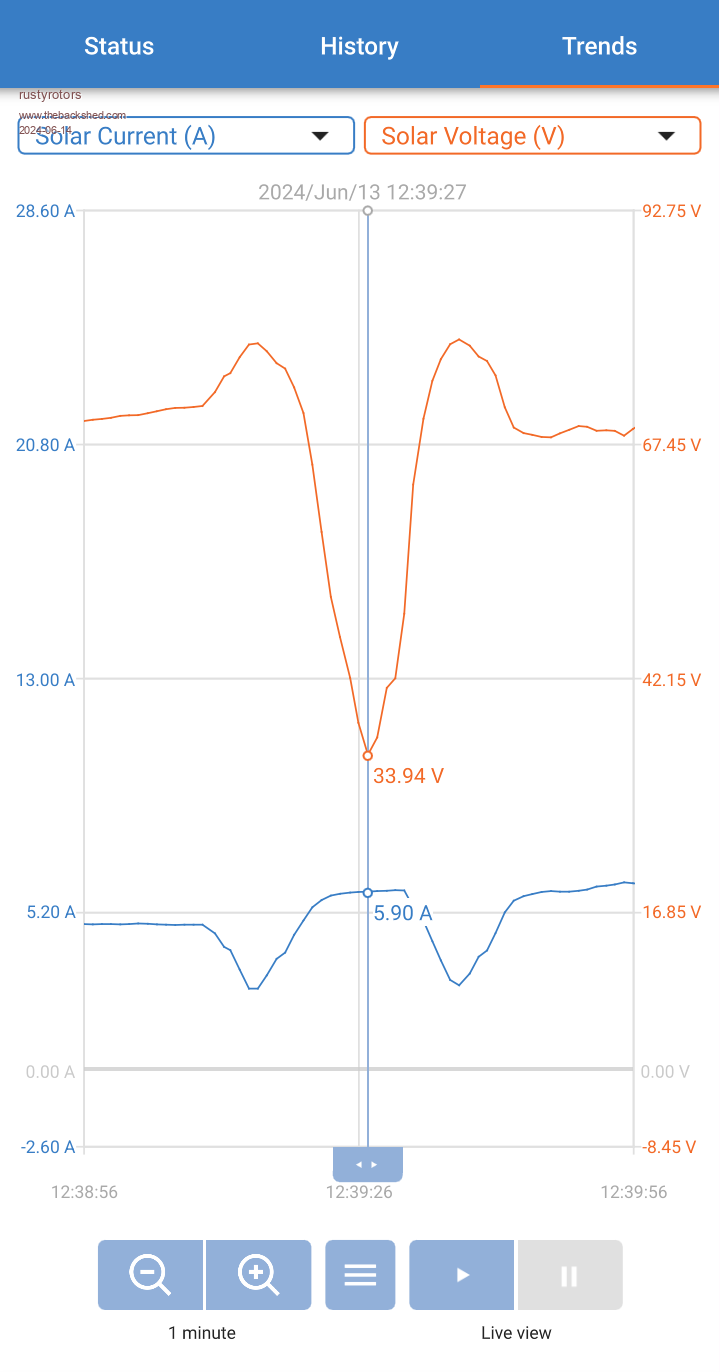
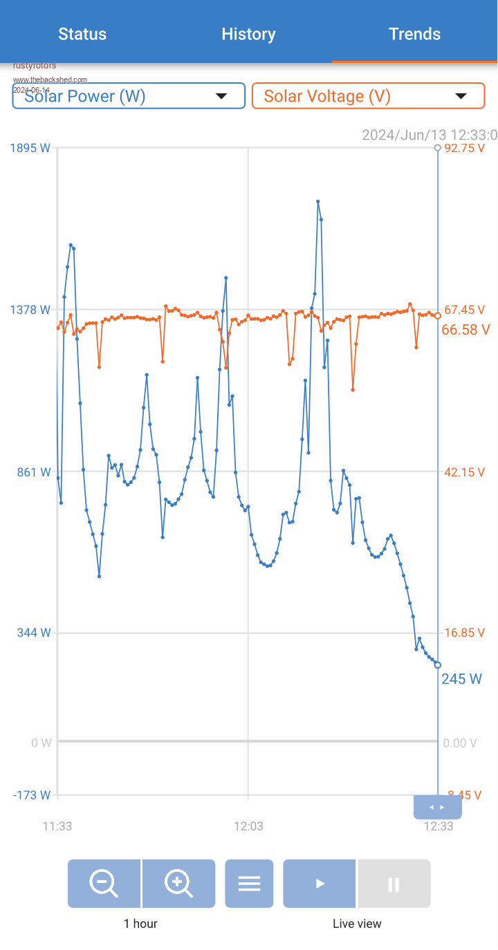
Yea i noticed the mppt resets every 10min, probably in case it gets stuck in a local maximum. Here are shots from my 150/100 at 24v battery, it doesnt short either. I think poida is seeing a different problem