Notice. New forum software under development. It's going to miss a few functions and look a bit ugly for a while, but I'm working on it full time now as the old forum was too unstable. Couple days, all good. If you notice any issues, please contact me.
phil99 Guru Joined: 11/02/2018 Location: AustraliaPosts: 1785
Posted: 11:09pm 07 Apr 2024
Copy link to clipboard
Print this post
P = I^2 x R so I = √(P / R)
0.1Ω => 7A 0.05Ω => 10A 0.01Ω => 22A
analog8484 Regular Member Joined: 11/11/2021 Location: United StatesPosts: 89
Posted: 11:49pm 07 Apr 2024
Copy link to clipboard
Print this post
EG8010 over-current protection will trigger when it see 0.5V or higher across the sense resistor. So, you need to scale the resistor based on the max surge current (should be well above the max continuous current) you want to allow.
Ex: Vocp=Iocp * Rsense => Rsense=Vocp/Iocp
Vocp=0.5V Iocp=10A
Rsense=0.5V/10A = 0.05R
ramblin Newbie Joined: 26/03/2024 Location: United StatesPosts: 16
Posted: 01:24am 08 Apr 2024
Copy link to clipboard
Print this post
OK, I don`t do math well but based on that 0.03 should work If I expect 14-15 amps ? How about the 5 watts ? Hard to find much over 15-20 watts and thats a fraction of the maybe 15amps available. What am I missing here ?
phil99 Guru Joined: 11/02/2018 Location: AustraliaPosts: 1785
Posted: 03:50am 08 Apr 2024
Copy link to clipboard
Print this post
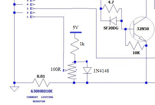
A possible work-around to allow the 0.01Ω shunt to achieve the 0.5V trip point at an adjustable current. The voltage divider adds a bias voltage to the voltage across the shunt. With the pot wiper at the top the current limit should be about zero, increasing as it is moved down to 50A at the bottom. As the 0.01Ω shunt is rated at 5W this could be used at up to 22A without overheating the shunt. Others with hands-on experience with these modules can advise if this will work the way I imagine.
ramblin Newbie Joined: 26/03/2024 Location: United StatesPosts: 16
Posted: 07:17pm 19 Apr 2024
Copy link to clipboard
Print this post
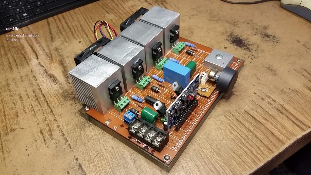
OK Guys, I have completed my inverter build. I have not yet hooked it up and applied power. I have to the best of my ability followed my schematic and doing a final check for any mistakes I made. I`m hoping the gurus here will do the same with my schematic. Any final additions or changes please. Do not assume I know anything. Thanks guys, Have a look.
tinyt Guru Joined: 12/11/2017 Location: United StatesPosts: 431
Posted: 02:06am 20 Apr 2024
Copy link to clipboard
Print this post
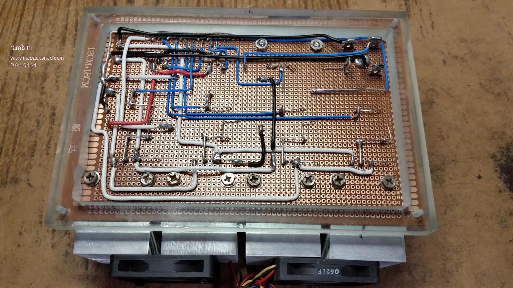
Since this is on proto-typing board, and the bottom is not shown, I hope the high current paths are beefed up. It is a very nice arrangement. Edited 2024-04-20 12:07 by tinyt
ramblin Newbie Joined: 26/03/2024 Location: United StatesPosts: 16
Posted: 02:22pm 20 Apr 2024
Copy link to clipboard
Print this post
Everything with any current is Teflon coated silver plated copper 18ga. Light stuff is 20.
rustyrotors Newbie Joined: 07/01/2023 Location: United StatesPosts: 31
Posted: 10:32pm 20 Apr 2024
Copy link to clipboard
Print this post
im not sure if anybody mentioned it yet, but make sure you remove U4 and short C19 on the EGS002 board, or it will destroy your fets if you trigger the overcurrent protection
ramblin Newbie Joined: 26/03/2024 Location: United StatesPosts: 16
Posted: 05:49am 22 Apr 2024
Copy link to clipboard
Print this post
Yes, nickskethisniks has warned me "people had bad experience with the current feedback..."and I believe I have a problem with it now. Is that the best way to deal with it, Just remove the chip? Huh? I have a spare board on the way and I can try that later. Happy to say I have my inverter WORKING (with issues) and I`m going to need a little help solving them. I have been testing at low power (about 50-60vdc@approx.1/2 amp). I am getting AC output but wildly fluctuating to the point of unable to get an accurate reading. Feedback voltage to pin 15 is also fluctuating between 2-4 volts. IMO, it seems inaccurate feedback and it can`t settle on anything, and with good reason. Before I found this forum I copied many variations of this circuit before someone here pointed me to the originals in the EG8010 data sheet. I may need a better current feedback circuit. For instance, I`m using a FWBR at the output to feed my variable resistor. The only circuits that use that, have transformers, which I hadn`t planned to use. Should I use the method found in the EGS002 manual (no bridge) and what values for the components? The values for the resistors and cap are different on every example. The EGS002 is steady red light (ready) in about center position. Turn one direction and the board goes offline. Turn the other direction and the EGS goes into protection mode, flashes twice and repeats (indicating over current). I`m not ruling out I still could have something connected wrong. I have already experimented, changing some component values from the last pic and added the loops to pins 5 and 9. Anyway I think I`m off to a good start. Just need a little more help. Some things have changed from the last circuit I posted. Happy to update it all just got so much bad info posted here already. Is there any way to delete some of it or that that not even an issue ? Thanks guys
wiseguy Guru Joined: 21/06/2018 Location: AustraliaPosts: 995
Posted: 06:53am 22 Apr 2024
Copy link to clipboard
Print this post
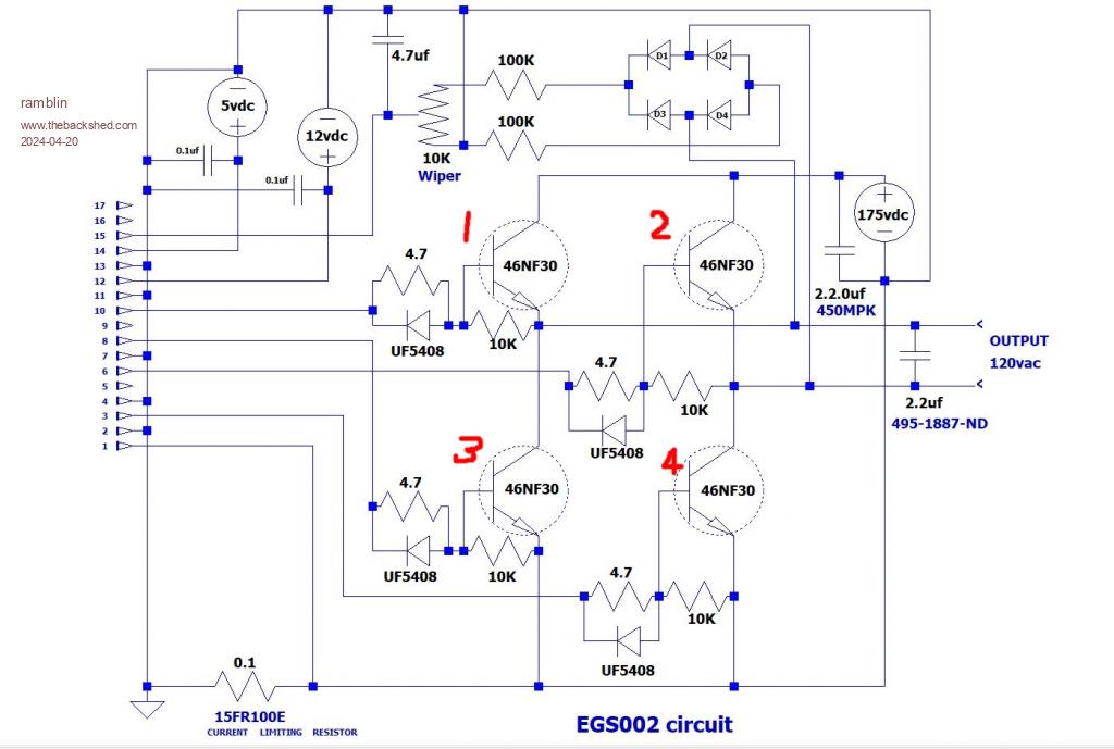
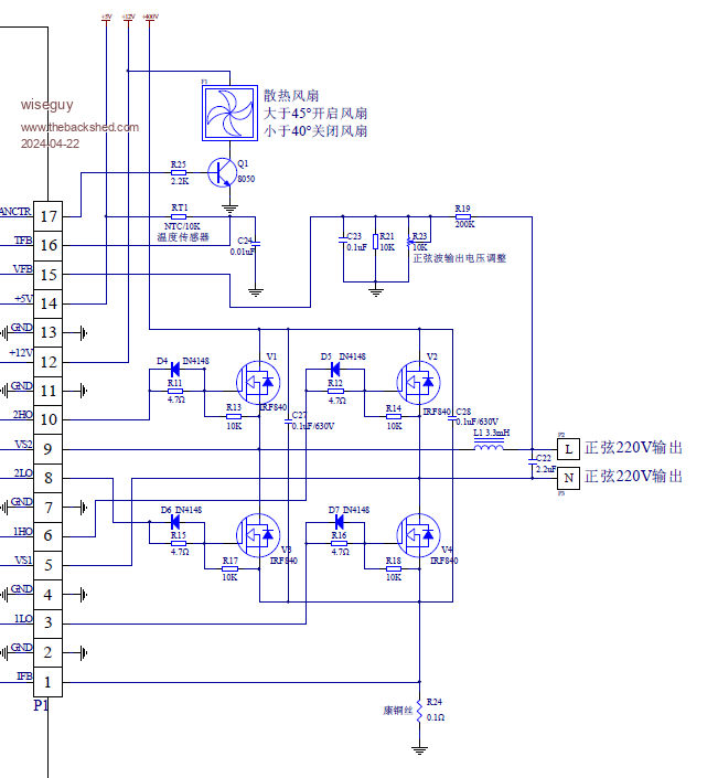
There are a few major issues with your schematic, I have posted a reference schematic from the EG8010 data sheet. You dont have connections (or they are not shown as connected) from the bridge to the EGS002 pins 9 or 5. The next problem appears to be the feedback you have used. If you implement the feedback - note it only uses the one bridge connection that connects to pin 9 of the EGS002 AFTER the missing choke on your board and the schematic (L1 -3.3mH), that should be between the 2u2 mains filter and the bridge that joins to pin 9.
It looks like you are aiming for 110/120VAC so change the value of R21 in the reference schematic to 56 or 68K to have a similar range as the 220V one. Also note they do not use a 4u7 for filtering the feedback but a 100n.
From their data sheet;
"Figure 8.1b is the actual testing wave under unipolar modulation. EG8010 uses the peak point sampling to output voltage, which has advantages of accurate voltage stabilization and short voltage adjustment time. If output voltage is deviated by some reasons such as change of load or input voltage, EG8010 can recover to expected output voltage in one to three AC cycle."
With those changes you have a better chance of making it work, good luck! To get it working, after making the connection changes, you could remove the 2u2 from your board then put the choke and 2u2 after the terminal block, but you would also have to then feed back the voltage from the choke/capacitor node of what is then the new ac output node. (if this doesnt make sense to you dont worry just make the above changes)
I have not studied your work in depth so I am not saying all else is right - it might be, I just noticed a few glaring issues, but if problems persist post again with whats happening. Edited 2024-04-22 17:06 by wiseguyIf at first you dont succeed, I suggest you avoid sky diving.... Cheers Mike
rustyrotors Newbie Joined: 07/01/2023 Location: United StatesPosts: 31
Posted: 10:51pm 23 Apr 2024
Copy link to clipboard
Print this post
also i believe you need the 5v, 12v, 175V grounds connected directly to ground, not through the current sensing resistor. else the egs002 will not see any voltage drop and wont know to shutdown for overcurrent. the current sense resistor is only inline with the mosfet bridge source returns
i use a small 240v/5v transformer for voltage feedback, 5v side connects to full bridge rectifier, then to a 10k pot, then to the 4.7uF or 100nF will work too as mike suggested. that way the ac output is fully isolated from battery negative, that way you can connect any output and/or battery negative to your solar system ground and not affect ac feedback circuit
wiseguy Guru Joined: 21/06/2018 Location: AustraliaPosts: 995
Posted: 01:35pm 24 Apr 2024
Copy link to clipboard
Print this post
Might as well add the voltage feedback ground to the list of things Rusty mentioned, to go to the other side of the current sense resistor - just cut the line below the 175V power supply and the 2.2.0 ? uF connection (on the schematic) and reconnect it to the LHS (ground) of the current sense resistor. Note their schematic uses 2 x 100n capacitors across each leg of the bridge top drain to bottom source. Why have you drawn the bridge semiconductors as transistors instead of FETs, when I put in the part number 46NF30 it returns a FET.
Now for the really really sad part, I think you will be very lucky if the FETs and maybe other parts are still alive. It looks very much like you have wired the gate drives to the drains of the FETs and the other FET connections are not right. Very easy to unsolder the gate/drain connections you made and shift them to the left (check on that it gave me a headache doing reverse upside down 360 orientation to my tired head), and then fix the remaining connections, if the centre of the 3 pins are the Drains the rest should be pretty easy to sort. The FETs gate/source votage has probably been exceeded you should disconnect the 4 FETs totally and check them for correct operation - I hope you know how to do that.....
After seeing that enormous bridge rectifier too I had to check the date in case it was all posted on 1st - I hope you get it sorted and not too many parts suffered! If you are really getting some sort of output - it has me a bit stumped how - there must be some trickery that is hidden. Edited 2024-04-24 23:40 by wiseguyIf at first you dont succeed, I suggest you avoid sky diving.... Cheers Mike
ramblin Newbie Joined: 26/03/2024 Location: United StatesPosts: 16
Posted: 03:12pm 24 Apr 2024
Copy link to clipboard
Print this post
Its time I addressed some of this. Rusty pointed out the ground problem and 1st thing I thought was to cut the line right below the power supply. I have always had problems understanding grounds and mentioned that early on. I asked a lot of questions about the current sense resistor and I`m still confused, but got a 0.05 in there as "nick" advised. Fixed that part. #2..I just use the LTSpice program to draw and don`t always get it right. Sorry bout that. I do have that parts hooked up right with 46nf30s. ..#3...Your right !! I had everything hooked up wrong and blew all my fets right off. Made the corrections, and actually got it working with some IRF740s I had. I was a rookie mistake and I learn from that. Got new 46nf30s coming with chokes & resistors. I said from the beginning don`t assume I know anything...#4.... I asked about the bridge in my last post. I copied much stuff from wrong from incorrect schematics because I didn`t know. (posted a bunch of bad stuff too !). I removed the bridge and am getting everything exactly like the drawing wiseguy posted before I try anything else. Please keep pointing this out to me. I`m here to learn and I won`t waste anyones time. I intend to make this work and never just quit. Keep straightening me out guys!
wiseguy Guru Joined: 21/06/2018 Location: AustraliaPosts: 995
Posted: 01:51am 25 Apr 2024
Copy link to clipboard
Print this post
That is the right attitude ! Everything happens for a reason you just need to find the reason. I can assure you in my early days I probably made similar mistakes as you have but its all part of the process. I am also tenacious & have the mantra that failure is not an option, so I persevere - recently I installed some TO92 transistors backwards (the silkscreen was wrong for the transistors in the PCB CAD), some TO92'S have the two outside (C & E) pins reversed, but the kicker is sometimes they can still work or partially work albeit with very low gain. It just illustrates that electronics has many traps and gotchas no matter how many years you've been at it or how good your skills are, just keep learning.
When you are ready to power up your inverter next time, leave the L1 (3.3mH) choke off to start with and set your current limit to ~ 30mA - I am asssuming you put a low voltage like 16 or 24V into the blue terminal block? If the power supply droops to below its initial V setting check your circuit before adding another 30mA if it still droops there is probably something still amiss dont exceed 90mA before finding out what is wrong. Use your CRO to check the +5V and +12V connections with respect to ground are smooth & without ripple or oscillation. You dont need +120 volts applied to the FET bridge to check its function just wire the +120V connection to the same +16 or +24V supply, then check the two bridge outputs with the CRO one should be a 50Hz squarewave the other a much faster "hash" waveform. These will only be available to see for maybe 20 or 30 seconds before you need to remove power and reapply to try again.
There are other ways to fool it to keep going but the above is a good starting point.
So far so good ? Now connect the the output choke & carefully connect the CRO across the 2u2 capacitor after the choke - if its a portable CRO thats fine if its a mains powered CRO ensure the ground pin is not connected to ground for this test or that your power supplies negatives are not grounded to mains ground - one or the other and you should now see a few sinewaves each time before it shuts down, the p-p voltage is roughly the same as the voltage applied to the +120V (16-24V ?). If that is still ok now you can connect the +120V input to a higher voltage and try again. Last advice before powering up at the high voltage set the trim pot so the wiper is not at the ground end but at the R19 end. The mains might only be say 70% of what you are after but if it all looks good then adjust the pot to increase the output.
Now is the time to consider placing a decent size electrolytic close to the +120 and ground pins of the connector, at least 470u to 1000u for best performance. I would not be expecting much more than maybe 1kW anything much above that is a bonus. Efficiency measurements are the best way to determine if you are pushing it too hard.
I have confidence you will post soon/eventually with some better news. Edited 2024-04-25 20:35 by wiseguyIf at first you dont succeed, I suggest you avoid sky diving.... Cheers Mike