Notice. New forum software under development. It's going to miss a few functions and look a bit ugly for a while, but I'm working on it full time now as the old forum was too unstable. Couple days, all good. If you notice any issues, please contact me.
ramblin Newbie Joined: 26/03/2024 Location: United StatesPosts: 39
Posted: 04:18pm 27 Mar 2024
Copy link to clipboard
Print this post
Well guys, I like this place already! Been browsing the threads and I find a lot of stuff that interest me. I`m here because there seems to be more talk about inverters than anywhere else and I`d like to build one. Hope the members here can help. I have an "experimental" Permanant magnet DC generator I built myself and I`d like to build an inverter to go with it. Its a work in progress is and prone to wild mood swings occasionally, so an off the shelf inverter will never work here. I have so far lit about 1000 watts of light bulbs with unclean power but believe it capable of more. Output voltage is determined by speed but also on how I connect my coils. Right now I have chosen 40-60vdc range (about as low as I can go) because I originally intended to use a common 48vdc to 120vac of the shelf inverter. I can step up voltages in stages to close to about whatever I need but hitting and staying on an exact target voltage is more difficult. Most circuits I find use batteries, often 12vdc and are 220vac. Problem is, I lack the skills to convert most circuits out there. I want something simple with no over/under voltage protection, buzzers, est. Something that can take a little abuse and easy for me to fix. I chose to use the EGS002 module, and a common drive circuit often associated with it. I believe it will need more mosfets among other things I don`t know how to do. I can follow a schematic and build on a breadboard or prototype board but thats about my limit for now. I just don`t know how to compute values or design anything. Maybe someone here has proto PCBs that would work for me. Looking for some advice on how to proceed......
mab1 Senior Member Joined: 10/02/2015 Location: United KingdomPosts: 282
Posted: 06:06pm 27 Mar 2024
Copy link to clipboard
Print this post
Hello, and welcome.
Are you wanting an inverter to run off your gererator without a battery? That's possible of course but would likely limit what you can run on the inverter, and you may have to limit the voltage range of the dc to some extent to protect the inverter.
A battery or very large capacitor would generally make life simpler unless the generator has a fairly stable voltage range. It might help to know how you're powering the generator. Edited 2024-03-28 04:06 by mab1
nickskethisniks Guru Joined: 17/10/2017 Location: BelgiumPosts: 477
Posted: 07:02pm 27 Mar 2024
Copy link to clipboard
Print this post
Do you want to build something with things you have laying around? Budget? You have some testing gear? (oscilloscoop, voltage/current meters)
There are lot's of ways to achieve what you want. On what rpm is the generator running and how many phases?
You can boost the voltage with a boost converter or smps to +-180V and then use 4 igbt's and LC filter to make you 120VAC.
Alternative you can use a toroidal or other type transformer like most of us to convert your low voltage AC to 120VAC.
Both possible with the egs002 module.
ramblin Newbie Joined: 26/03/2024 Location: United StatesPosts: 39
Posted: 07:09pm 27 Mar 2024
Copy link to clipboard
Print this post
That is correct. It is powered by variable speed electric or gas (I have both) but for bench testing I use a big DC variable speed motor. Now load, lentz, speed and even capacitors can vary the output. But under a given load I can control the output pretty well. That being said, even a bulb blowing can lead to higher voltage and several more blown with out a speed change and it can happen fast.
ramblin Newbie Joined: 26/03/2024 Location: United StatesPosts: 39
Posted: 08:54pm 27 Mar 2024
Copy link to clipboard
Print this post
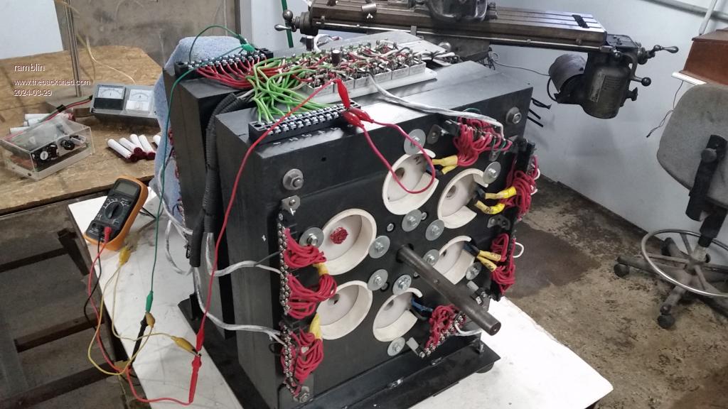
OK, Lot to unpack there. Let me get you guys up to speed. Yes, I have basic testing gear. Not really on any budget and I do have a lot of parts as well as transformers and a big toroid that might be perfect. Now on to output....Where to start?. The gen is really a neo magnet alternator. 12 coils (6 pairs tied together, usually) output 6 phz AC @150 to 300 hrz. at speeds up to 3200rpm with a sweet spot near 23-2400rpm. Thats a mouthful. This will produce a noisy sine wave on my scope but believe me its a mess. Each coil and core can vary slightly making it difficult to "blend" these AC freq. together properly. However, I have powered a bunch of incandescent light bulbs @ 900 to 1000 watts for extended periods of time. I have powered many of my collection of stepup/down transformers also with varying results. Always an iratical, inconsistent, "inefficient" (IMO destructive) sinewave. I chose to try DC. I added a full wave bridge rectifier to each coil. It just made sense as I can add small caps on the AC side to trim each coil for a more consistent voltage or the DC side to filter. So far I have only wired 2 opposing coils for what I call my 50-60vdc range and tested independently with a load. And when added in parallel, produce no voltage change but add in amps to the load. This seems better. This is where I`m at now. Is this to much to digest ? I could go on.... Can we add pics here ?
phil99 Guru Joined: 11/02/2018 Location: AustraliaPosts: 3293
Posted: 09:17pm 27 Mar 2024
Copy link to clipboard
Print this post
An interesting project. Some years ago I did some repairs on a 2kW inverter generator and it does the sort of thing you describe. The 3 phase permanent magnet alternator fed a 6 diode bridge rectifier producing about 350VDC. The 230V inverter section used 1000V IGBTs.
Primary coarse voltage regulation was via a servo actuator controlling the engine governor. Fine voltage regulation was the inverter feedback system.
The high voltage rating of the IGBTs was probably to cater for the voltage swings you observe.
To get a better idea of how to go about this perhaps get a few service manuals / circuit diagrams for various inverter generators.
Footnote added 2024-03-28 09:36 by phil99 A point I missed above is the engine governor servo actuator is controlled by feedback from the rectifier output. It tries to maintain 350V, however the engine can't respond very fast so there are significant fluctuations when loads are switched.
ramblin Newbie Joined: 26/03/2024 Location: United StatesPosts: 39
Posted: 09:41pm 27 Mar 2024
Copy link to clipboard
Print this post
Another thing, to be clear this is never intended to be hooked to the grid. This is just a project I want to see how much useable power it can make as opposed to how much I put into it. Its a tried and true design found all over youtube. Its not cutting edge design but its a reliable design and is able to make a lot of power very efficiently. Most spin rather slow as anyone thats played with neo mags knows they can create a lot of heat. Most are not foolish enough to spin at the speeds I am.
ramblin Newbie Joined: 26/03/2024 Location: United StatesPosts: 39
Posted: 08:44pm 28 Mar 2024
Copy link to clipboard
Print this post
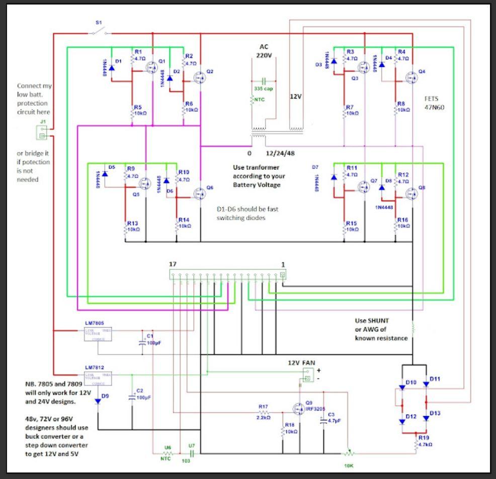
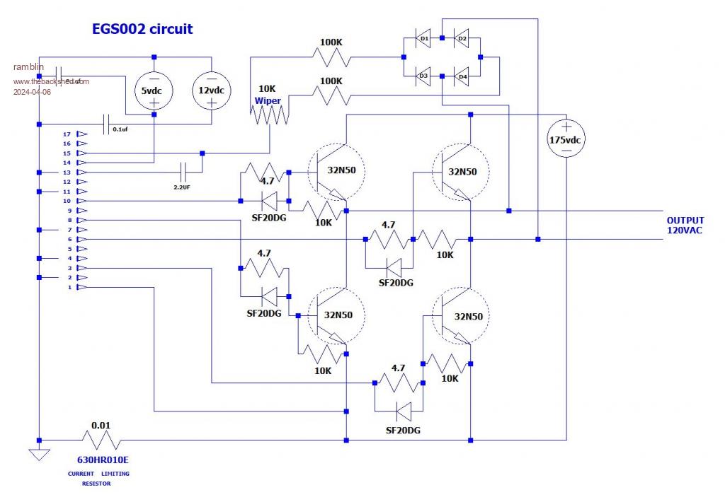
Maybe a pic will help. At least it shows I`m serious. This is the circuit I`d like to convert to work for me, but I need a little help. Works with the EGS002.
ramblin Newbie Joined: 26/03/2024 Location: United StatesPosts: 39
Posted: 04:05pm 30 Mar 2024
Copy link to clipboard
Print this post
OK, I`m not getting the feedback I had hoped for so let me try so pointed questions...... Lets assume I can maintain a stable voltage and with the wiring configuration right now, that is about 50vdc. My target would be 120vac @60hz.
#1.. Would the circuit I posted work with some modifications for some testing ? Probabley needs to handle about 15amps. #2 .. Would this circuit need more mosfets to handle 15 amps ? #3 .. Would 48-50vdc be optimum as I have higher voltages available ? #4 .. Is anyone here able to give me some guidance, Maybe sketch out something for me ?
mab1 Senior Member Joined: 10/02/2015 Location: United KingdomPosts: 282
Posted: 07:40pm 30 Mar 2024
Copy link to clipboard
Print this post
Ok,
For starters, if you want 120v a.c. puresine then if you can wire your generator for 175 - 200 v instead of 50v then your egs002 can generate the desired 120v a.c. waveform directly without a transformer. Usual caveat that playing with higher voltages can get you killed - don't do it unless you're competent to do so. Although, depending on what you're doing with the output you might want a transformer for isolation anyway.
I assume you want 15a at 120v? If you follow the above suggestion then you could manage fine with 4 IGBTs (better at high voltage than FETs probably). If you're sticking with 50v d.c. then you can still manage with single FETs as that's about 40A max at 50v by my reckoning, and there are plenty of FETs that can easily handle that. I.e. you can manage with fewer FETs than the circuit you posted. Edited 2024-03-31 05:42 by mab1
mab1 Senior Member Joined: 10/02/2015 Location: United KingdomPosts: 282
Posted: 07:59pm 30 Mar 2024
Copy link to clipboard
Print this post
That's was sort of my answer to q2 and q3 i suppose.
Q1: i don't know. If you can keep the voltage from the generator stable (how stable?) and your a.c. loading is stable (?) Then a standard egs002 circuit should work as is. But without knowing what the a c. Loading is going to be or how stable the generator is going to be i can't answer your question. Without a battery or very big capacitor you're going to be a bit limited in what you can do with it.
Q4: not really - the only 'mod' i could suggest is use a very big capacitor in lieu of a battery. Edited 2024-03-31 06:00 by mab1
ramblin Newbie Joined: 26/03/2024 Location: United StatesPosts: 39
Posted: 08:39pm 30 Mar 2024
Copy link to clipboard
Print this post
Thanks mab1, So if I generate a steady 175-200vdc and use the EGS002 and this circuit this would get me in the 120vac range ? Is that correct ? If so ,I do have a 120vac isolation transformer I could use. My understanding of components is limited but would luv to try the circuit with IGBTs but have never worked with one in my life. Could you make some suggestions (sketch) on modifying this circuit. I understand how to add my own 12vdc and 5vdc but am unclear on how to ground everything and keep the board isolated .
nickskethisniks Guru Joined: 17/10/2017 Location: BelgiumPosts: 477
Posted: 09:00pm 30 Mar 2024
Copy link to clipboard
Print this post
Wow, didn't expected to see a nice generator, well done
Feedback will be little this moment of year, a lot of people have holidays now and many people are quit bussy finishing their own creations, lots of stuff in the pipeline.
Ok, the schematic should work, but you should power your electronics from a steady powersupply. For testing you can use a small 12V battery or psu, don't use the power the generator gives at this stage.
Do you have some mosfets? IGBT's most often need a negative bias when turning off. So, I would look for at least some 100V-150V mosfets because of the fact it is difficult to get the dc voltage stable at the moment? Will you use those 47n60 mosfets mentioned in the schematic? Those should handle 15A just fine, but they must be mounted on a heat sink, isolated with for example mica or other pads. Maybe look for something stronger then the 1n4448 diode, it's only 200mA. Something around 1A will be more robust.
The higher the voltage the better for those mosfets from the schematic, you can test this even without an output transformer. Use an LC filter to smooth things out, look for something around 1mH and 10uF.
Or use a transformer suitable according to your output voltage. 50VDC will give you roughly 35V AC when filtered. (there is a factor 1.41 involved, if you rule out the other losses)
Running your H bridge straight from the rectified generator voltage will not work, you will need at least some capacitance, without this you will be replacing mosfets faster then you can buy. Without some capacitance the hf pwm will create very high voltages between drain and source because of the inductance involved. I would start with at least 10000uF and a small value mkp 4,7uF in parallel for 1kW. Connect your generator for at least 3 phases that way you have small ripple on the capacitors.
ramblin Newbie Joined: 26/03/2024 Location: United StatesPosts: 39
Posted: 06:06pm 31 Mar 2024
Copy link to clipboard
Print this post
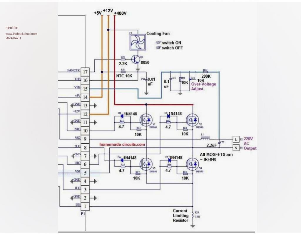
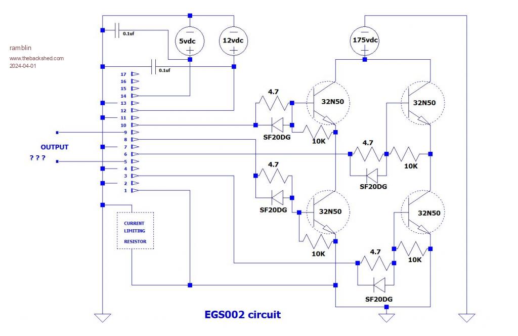
Well thanks for the response" nickskethisniks", this is the kind of help I need. Did a little testing last night and I do have a nice window at 175-185 vdc. @ around 550 Hz. Since" mab1" indicated I could get by with less mosfets (I thought I would need more) I copied another EGS002 circuit using only 4 fets. I left off the fan circuit for now and use my own heatsinks and fan. Is pin 15 necessary to do some testing ? Don`t know how to hook that in. Does my AC power come from pins 5 and 9 on the EGS002 ? That many amps, I can`t have that right. Not sure how to ground everything and isolate the EGS002. I wouldn`t know what kind of current limiting resistor to use either. I`m sure some other caps need to be added. Much here I don`t know how to do. I made a schematic of what I do know and attached a copy of the circuit I copied from. Any help here would be much appreciated. Don`t assume I know anything.
mab1 Senior Member Joined: 10/02/2015 Location: United KingdomPosts: 282
Posted: 08:06pm 31 Mar 2024
Copy link to clipboard
Print this post
Pin15 is the voltage feedback circuit - you need to adjust that to set the output voltage. As that circuit looks to be for 230v a.c. i would suggest dropping the value of R19 from 200k to 100k as you're aiming for 120v.
Pins 5 and 9 are connected to the two sides of the HBridge and will have the full 120v a.c. on them - this is needed for the high-side driver circuits. But the output current doesn't pass through the pins - you take that from the h-bridge FETs (shown going off to the right in the diagram).
You would have to download the datasheet for the egs002 to work out what the feedback resistor should be, but it might not be too important as you're output current is going to be limited by what your gererator can produce anyway.
nickskethisniks Guru Joined: 17/10/2017 Location: BelgiumPosts: 477
Posted: 09:01pm 31 Mar 2024
Copy link to clipboard
Print this post
That grounding point, just under the sf20dg diode should be removed otherwise you short out the current sensing resistor.
If you are running for 180VDC you won't needing 10000uF to test with, something like 1000uF will do, but keep in mind this capacitor should be rated for at least 2A ripple current depending on the output inductor. (this is for calculation with about 8.5A, 180V bus and 1mH, 10uF )
This is a nice article for heaving some understanding:
Yes pin 15 is necessary for testing, if it's not sensing output voltage it will try start by widening the pwm dutycycle and repeat this a few times before shutting down. You can fool this pin to connect a potentiometer between the ground and 5V and connect the wiper to it. I think it want's to see 3V.
For the current this is 0.5V, people had bad expierence with the current feedback, try not to make short circuits in the first place.
To get familiar with the circuit you might want to test it first on lower voltages. Edited 2024-04-01 07:10 by nickskethisniks
ramblin Newbie Joined: 26/03/2024 Location: United StatesPosts: 39
Posted: 05:57pm 01 Apr 2024
Copy link to clipboard
Print this post
Thanks guys, You`ve given me a lot to think on. I need to comprehend all this and read up on the data sheets. I got parts on the way. Probably draw up something with the corrections made and get back with a few more questions before I get to far into it. Just stay with me and I will post progress along the way. Hopefully in the end I`ll have something. Thanks guys !
ramblin Newbie Joined: 26/03/2024 Location: United StatesPosts: 39
Posted: 04:26pm 05 Apr 2024
Copy link to clipboard
Print this post
OK, couple of things as parts are arriving and I`m about to start putting something together. Could someone have a look at this updated schematic and point out anything that needs to be corrected. Still unsure about the current limiting resistor. Is the value correct and is it in the right place ? I also added the control to pin 15 from even another circuit I found and it had a bridge rectifier in there. Is this correct ? Also it was mentioned that I need a 1000uf cap to test. Is this across the DC output before the circuit ? I have 3 polarized caps that could work. A 1000uf/250V, a 1000uf/200V and a 2200uf/200V. Would and of these work ? I do have a 120vac medical grade isolation transformer I was planning on using. All advise appreciated, Thanks.
Edited 2024-04-06 02:40 by ramblin
nickskethisniks Guru Joined: 17/10/2017 Location: BelgiumPosts: 477
Posted: 08:44pm 05 Apr 2024
Copy link to clipboard
Print this post
I think there might be a problem in your voltage feedback circuit. Take a look at p9 of the datasheet. Your missing a ground connection.
No the current limit resistor should be higher in your application, I would start with 0.05R-0.1R, this is good for 10A to 5A (0.01R is for 50A) wich is high enough for you at the moment, the chip will go in protection at 0.5V, make sure you use something like 1n4007 for d1-d4 to handle the voltage.
Those capacitors will work, as close to your mosfet bridge as possible, an extra small value (a few uF) capacitor parallel with low esr/esl like mkp is advisable. Edited 2024-04-06 06:46 by nickskethisniks
ramblin Newbie Joined: 26/03/2024 Location: United StatesPosts: 39
Posted: 10:49pm 07 Apr 2024
Copy link to clipboard
Print this post
Ok, so I`ve made the suggested changes to my circuit as per page 9 of the data sheet so lets assume I got it right this time. I wasn`t aware the eg8010 data sheet was the egs002 and had the circuit everyone was coping from. I missed that 1st time around. I won`t bother posting an updated one as I have enough bad ones posted and don`t see any way of removing them. Just don`t want to junk up forum space for nothing. Now I`m still confused on the current limiting/sensing resistor and maybe someone can explain its purpose and how I would arrive at a correct value for my use. Nick... has made some suggestions and I have "Ohmite current sense" 0.05, 0.1 and 0.01 on the way. These are only rated at 10, 50, and 100, mOhms. and @ 5 watts. I don`t really know how to determine the amp rating or what I need to achieve here, so a little more help would on this would be appreciated. I would seem to me the entire circuit, including the egs002 and pin 1 are expose to the high voltage/amps and only the ground is limited. Can you tell I don`t understand this part ? Thanks guys
Page 1 of 4
Print this page
The Back Shed's forum code is written, and hosted, in Australia.