
|
|
Forum Index : Electronics : Need help with my DC motor controller
| Author | Message | ||||
| Gizmo Admin Group Joined: 05/06/2004 Location: AustraliaPosts: 5182 |
Hiya guys. I'm using a couple 250 watt DC brush geared scoota motors on a rover. 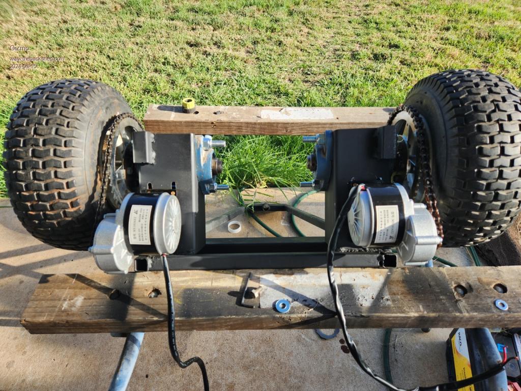 I found this circuit online... 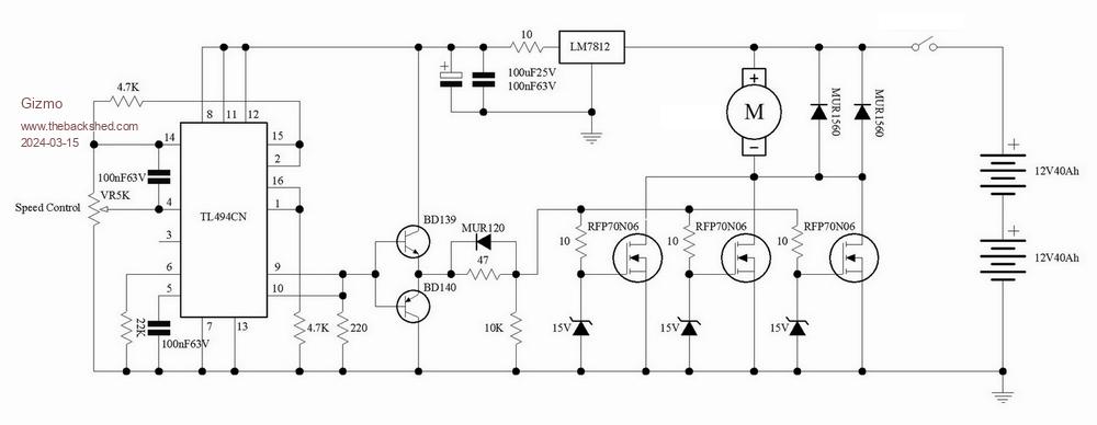 and made a few changes to suit my needs. I added a pair of relays to reverse the motor, and a opto coupler to give some isolation from the CPU providing the PWM signal. 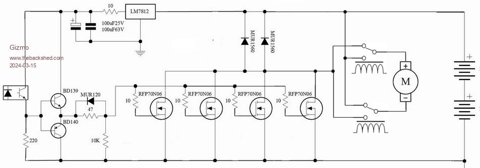 The PWM signal is clean, 16kHz. I've assembled 2 controllers, and it all appeared to be working fine. The mosfets run cold, even at full power. But then one motor went flat out and one controller went pop. Blew all the tops off the 4 mosfets. The mosfets are overrated for the current draw, and I know they are getting a clean square wave drive signal. There is a 30 amp fuse, its fine. I didnt include the 15v zener diodes on the gates of the mosfets, simply because I couldn't see what they were needed for. Any suggestions as to whats wrong with my circuit, how it could be improved. The load is inductive, could that be the problem, and do I address that? Are those missing zeners the issue? Glenn The best time to plant a tree was twenty years ago, the second best time is right now. JAQ |
||||
| oh3gdo Regular Member Joined: 18/11/2021 Location: FinlandPosts: 47 |
Gizmo I think that you have got too much current. The specs show about 350 A/us. You must add a small inductor to series of the fets. I it was my fault, when I was designing the first static SCR controllerr in Finland. It size was 30MVar and 10 kV. But when I limit current rise time to 100A/us with a small inductor, then it worked. Otherwise the circuit seems to be ok. http://capacitor.wikidot.com/ Pekka Ritamaki |
||||
| phil99 Guru Joined: 11/02/2018 Location: AustraliaPosts: 3293 |
The zeners are to protect the gates from inductive spikes. The gate is a capacitor so a sudden increase in voltage on the drain can induce a voltage on the gate that is higher than the gate-source breakdown voltage. They need to be very close to the FETs. As noted above small inductors in the drain legs, close to the FETs can reduce the rate of change. In one of the inverter threads they are using ferrite beads on the drain legs to good effect. In addition add a capacitor and series resistor across the motor to absorb commutation spikes. At a guess, at 24V and up to 30A I would use a 1µF to 10µF 63V plastic cap. and 2.2Ω 2W resistor. |
||||
| Gizmo Admin Group Joined: 05/06/2004 Location: AustraliaPosts: 5182 |
Thanks guys. All my drains are via the heatsink tabs, so cant fit ferrite beads to those, but can fit to the source pins, would that be ok. I'll add the zeners. I thought maybe they were there to keep the gate voltage below the safe gate specs, but its already got a 12v regulator. Didn't know about the induced voltage back through the fet. Glenn The best time to plant a tree was twenty years ago, the second best time is right now. JAQ |
||||
| phil99 Guru Joined: 11/02/2018 Location: AustraliaPosts: 3293 |
If putting the beads on the source pins perhaps solder the zener on to the FETs between the bead and the FET for best protection. May be overkill but easy to do. Had a rethink about the R-C across the motor. Perhaps 0.47µF to 2.2µF and 1Ω to 3.3Ω 5W for the resistor may be better at 16kHz.  Edited 2024-03-16 09:42 by phil99 |
||||
| Solar Mike Guru Joined: 08/02/2015 Location: New ZealandPosts: 1214 |
Placing an ferrite bead on your source pins will affect the gate drive signals, I wouldnt do that. You could add an inductance 100uH or so on the + supply lead from the battery, this will limit the motor current rise time and give the parallel mosfets more time to all turn on and share the current. To negate the inductance of the cables going to the battery, add approx 10,000uf electrolytic across the battery wires close to the motors. For the totem pole driver, the 47r resistor will slow down the mosfets, short it out and remove the diode, place a similar diode across each of the mosfets 10r gate resistors. Cheers Mike Edited 2024-03-16 12:18 by Solar Mike |
||||
| Gizmo Admin Group Joined: 05/06/2004 Location: AustraliaPosts: 5182 |
All the drains are electrically connected to the heat sink, then a terminal on the heat sink goes to the diodes and motor. Could I place the inductor on this wire to the motors? Revised circuit, how does this look. 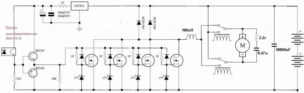 Glenn The best time to plant a tree was twenty years ago, the second best time is right now. JAQ |
||||
| phil99 Guru Joined: 11/02/2018 Location: AustraliaPosts: 3293 |
That looks good, perhaps with another 2.2Ω - 0.47µ from heatsink to ground. Belt and braces but costs less than another set of MOSFETs. Edit. Another thought, is the opto-coupler fast enough for the FETs? A scope view across its 220Ω load should have fast rise and fall. Test without the motor. Edited 2024-03-16 14:14 by phil99 |
||||
| Solar Mike Guru Joined: 08/02/2015 Location: New ZealandPosts: 1214 |
Looks ok, not sure about the opto coupler rating, it may have excessive current pulses as it turns on the BD139, pulling the base to 12v; perhaps place a 100r resistor in place of the link between the 2 base connection to the opto emitter. Mike |
||||
| phil99 Guru Joined: 11/02/2018 Location: AustraliaPosts: 3293 |
The minimum resistance of the opto is probably a few hundred ohms and the BD139 is quite rugged. The gate resistors and low gain of the transistors at high current will limit the peak to less than 4A. That should be fine for the µS it takes to charge the gates. Edit. The minimum resistance of the opto will affect how high the gate voltage goes. The scope will tell you that too. If it doesn't get to 10V add a PN100 emitter follower between the opto and the bases. The base of the PN100 can have a 2.2kΩ to ⏚. Edited 2024-03-16 15:07 by phil99 |
||||
| Gizmo Admin Group Joined: 05/06/2004 Location: AustraliaPosts: 5182 |
I did have a look at the switching with my cro, seamed very clean but didn't measure the rise/fall times. The opto is a PC817 ( I have stacks of them ), which can handle a collector current up to 50mA. I am tempted to ditch the opto and just use a BC547 on the ground side and put a 330r resistor to the +12 side. The whole thing is common ground so should be OK. As a fall back I do have this little beastie from a very old 5 axis robot. Its designed for a 2kW 3 phase DC servo motor. I would only need the bottom 2 drives for my rover. Maybe not as efficient as mosfets, but probably a lot more rugged. I have 3, so that's a couple spares. 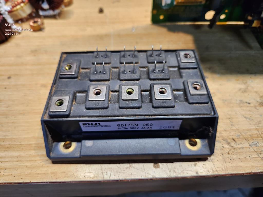  Glenn The best time to plant a tree was twenty years ago, the second best time is right now. JAQ |
||||
| phil99 Guru Joined: 11/02/2018 Location: AustraliaPosts: 3293 |
Checked the datasheet for the PC817 and with a LED current of 10mA, 1.4 volt drop with a 220Ω load and typical response time of 4µS should be ok. |
||||
| nickskethisniks Guru Joined: 17/10/2017 Location: BelgiumPosts: 477 |
Could you post a picture of the power board? Solar Mike suggested a 10000µF capacitor, but maybe a few µF of MKP capacitors really close to the mosfets could solve this issue as well. |
||||
| Solar Mike Guru Joined: 08/02/2015 Location: New ZealandPosts: 1214 |
Gizmo, do you have a link where those scoota motors can be purchased. We could use something like that to fit to a wheel barrow like contraption for moving large trays of potted plants around. Cheers Mike |
||||
| Gizmo Admin Group Joined: 05/06/2004 Location: AustraliaPosts: 5182 |
Mike I sourced them from this ebay seller - https://www.ebay.com.au/itm/314925389518 . There may be someone closer to you. They are 9.78:1 ratio, and I'm using a 48 tooth cog on the wheel. They have enough power to drive the rover at a fast walking speed, and guess the rover weighs around 70kg with its 2 12v deep cycle batteries. Sorry Nick no photo of the boards, they are on veroboard, been modified a few times, and ugly as a hat full of arseholes. I made most of the changes suggested above, but used only one zener, I could only find a handful of zeners in my collection, so will get some more in. The controller is working again thanks, see how it goes. If it lasts I'll make a proper PCB. Glenn The best time to plant a tree was twenty years ago, the second best time is right now. JAQ |
||||
| The Back Shed's forum code is written, and hosted, in Australia. | © JAQ Software 2026 |
