|

|
Forum Index : Electronics : "48V" Dump Load
| Author | Message | ||||
| solarwind Regular Member Joined: 03/02/2008 Location: South AfricaPosts: 51 |
Hi! Anyone out there with a simple, yet reliable circuit for a "48V" Dump load for use on wind and/or solar? (Should be able to be adjusted to about 56.8V). Thanks! JH. You don't have success until you've tried it! |
||||
| Gizmo Admin Group Joined: 05/06/2004 Location: AustraliaPosts: 5078 |
You can make one easily enough. See Pete's article, using oven elements. http://www.thebackshed.com/windmill/articles/BuildingEncapsu latedResistors.asp For 48V, I would leave the elements intact and test it out, see how much power it draws and if it gets too hot to use safely. You can pick up 2nd hand elements from most tip shops for a couple dollars. How much power do you want to dump? Glenn The best time to plant a tree was twenty years ago, the second best time is right now. JAQ |
||||
| solarwind Regular Member Joined: 03/02/2008 Location: South AfricaPosts: 51 |
Thanks Glenn! I have seen this one, thanks. My actual problem is to step-down from the raw "48V" into whatever I use (electronics voltage monitoring with say op-amps with power supply of 8V). Looks like I shall have to use some pre-regulators, one after the other to make up for the high differential voltage, or do you have some other solution in mind? Regards, Johann. You don't have success until you've tried it! |
||||
| powerednut Senior Member Joined: 09/12/2009 Location: AustraliaPosts: 221 |
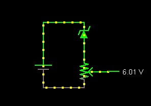
I'm not quite sure what your trying to achieve - are you just trying to get the voltage down to a level that you can monitor with the op amps, or are you trying to provide the 8V to your monitoring circuit (or whatever else you want to run)? If your just trying to get the voltage down to a level that you can monitor with the op amps you might want to look at using a 43 or 47 volt zener diode and a variable resistor (trimpot), much like ghurd uses in his dump load controller. The wiper of the trimpot would be the input to the op amps. Should be pretty damn cheap. 
In the image the zener is a 47V, the battery is at 60V and the trimpot is a 5k. If your powering small circuts I'd be inclined to build a small buck (step down switchmode converter) power supply to drop the voltage from 48V to whatever you want to use. There are a bunch of fixed and adjustable regulators available in the $3-4 range. There is a good video tutorial on how to design and build these circuits on the eevblog site (eevblog "lets design a smps" ). |
||||
| solarwind Regular Member Joined: 03/02/2008 Location: South AfricaPosts: 51 |
Hi powerednut, Yes, I need to source my power supply for my monitoring circuit from the "raw" DC of about 60V. From previous experience, I found that this cannot be done directly with the normal LM78XX type regulators, unless you put one after the other so that you never at any stage exceed the voltage differential allowed across each regulator. This works, but I think what you suggest in terms of a small buck converter, will allow me a low voltage supply without the unnecessary heat from the series regulators. Thanks once more for your support! Johann. You don't have success until you've tried it! |
||||
| Warpspeed Guru Joined: 09/08/2007 Location: AustraliaPosts: 4406 |
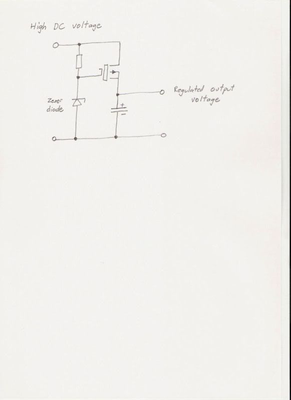
This is pretty easy. Use an N channel MOSFET of suitably high voltage rating, and a high value resistor/zener to fix the gate voltage. A regulator like this can provide +8 volts out with any input between maybe twelve volts and several hundred volts. It can also draw remarkably little power with little or no load connected. The gate threshold of most MOSFETS will be around three to four volts, so the zener may need to be about 11v to 12v for eight volts output. A bit of experimentation may be called for here to get exactly what you want. The resistor is not critical either, maybe between 10K and 1 meg. The voltage regulation will not be super tight, but certainly good enough for op amps, or some 4000 series CMOS logic gates. If you want really tight voltage regulation, increase the voltage a bit, and fit a proper voltage regulator after this circuit.  Cheers, Tony. |
||||
| solarwind Regular Member Joined: 03/02/2008 Location: South AfricaPosts: 51 |
Hi Tony, This is super, yet so simple! Thanks a lot! Regards, Johann.  You don't have success until you've tried it! |
||||
| Gizmo Admin Group Joined: 05/06/2004 Location: AustraliaPosts: 5078 |
Just built the circuit Tony posted and it works well. I also just noticed the symbol in Tony's circuit diagram shows a P channel mosfet, the arrow should be pointing the other way. Glenn The best time to plant a tree was twenty years ago, the second best time is right now. JAQ |
||||
| Warpspeed Guru Joined: 09/08/2007 Location: AustraliaPosts: 4406 |
OOPs, you are quite right about the arrow Glenn. But other than that, I have used this design in very low power commercial equipment and it has worked fine without any issues. Cheers, Tony. |
||||
| Gizmo Admin Group Joined: 05/06/2004 Location: AustraliaPosts: 5078 |
Yeah its a neat simple circuit. I've added it to the TL084 based controller http://www.thebackshed.com/Windmill/articles/TL084-Controlle r.asp. Glenn The best time to plant a tree was twenty years ago, the second best time is right now. JAQ |
||||