
|

|
Forum Index : Electronics : testing ultracapacitors
| Author | Message | ||||
| Tinker Guru Joined: 07/11/2007 Location: AustraliaPosts: 1904 |
My 12 ultracapacitors (3000F@ 2.7VDC) have been sitting under my bench for a week so I thought its time to put them to the test. I started by connecting 5 of them in series and charging them from my variable power supply (home built  ). ).
That was an interesting exercise in itself and shows that extreme caution is required with these caps. They arrived with no charge (a few millivolt) in each. The lowest my supply goes down to is 2.5V so I hooked the 5 caps up via an old moving iron 10A meter and a digital volt meter across the terminals. Turning the supply on the 10A meter's needle slammed hard over and stayed there for a while until the caps charged up somewhat. It would NOT be a good idea to connect an empty capacitor bank directly across a power supply or, worse, a battery bank - the effect is the same as placing a spanner across the terminals. Anyway, the old meter survived - it would have fried a digital Amp meter - and I then used a 0.47 Ohm/5W resistor in series for the charging process. This took quite a while, I watched the Amp meter needle creep back as the cap charged up and wound the voltage up a little each time the charge current dropped to 1 Amp. So the supply pushed 10A initially at each voltage increase and got hot enough for the cooling fan to come on. When the cap bank was charged to 12.6V I set the lot up for a 'real' test  , there are Utube video's aplenty of supercaps producing pretty sparks or vaporizing bits of wire , there are Utube video's aplenty of supercaps producing pretty sparks or vaporizing bits of wire  . .
See here what I did ultracapacitor test Watch the Amp meter and the Volt meter, its surprising how well the caps supplied what was required. I recon these caps can easily start a petrol car engine. Still to come is my voltage equalizer arrangement and the wall mounting & connection of the cap bank to my battery bank. Will post that in a day or two. I have since connected 11 ultracaps in series and 'carefully  ' charged them to 26VDC. Left them connected to the supply until no more charging current flowed into the caps. ' charged them to 26VDC. Left them connected to the supply until no more charging current flowed into the caps.
I then disconnected the cap bank and measured each cap individually - there were NO equalising components in place at that stage. There was a difference of up to 0.2V between the charged capacitors, indicating that some kind of equalising arrangement is indeed required if the caps are charged up close to their 2.7V rating. Klaus |
||||
| VK4AYQ Guru Joined: 02/12/2009 Location: AustraliaPosts: 2539 |
Hi tinker Maybe a headlight globe in series may be a simple way to charge the UC and give an indication as well, couldn't get your U tube test, but am awaiting your testing with interest as i am thinking of getting a set myself. All the best Bob Foolin Around |
||||
| Tinker Guru Joined: 07/11/2007 Location: AustraliaPosts: 1904 |
Hi Bob The link works for me but I put only unlisted video's on Utube so only those with the link can see it. You can try this: http://www.youtube.com/watch?v=OfL_8lsHPbM I have almost completed my ultracap set up now. First I made two PCB's 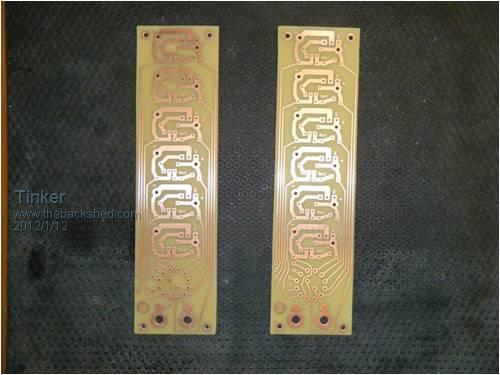
for the equalizing circuit. I used a simple high current shunt regulator that I saw in the Texas Instruments application notice for the TL431 adjustable precision shunt regulator. The complete arrangement, all wired up can be seen on this pic 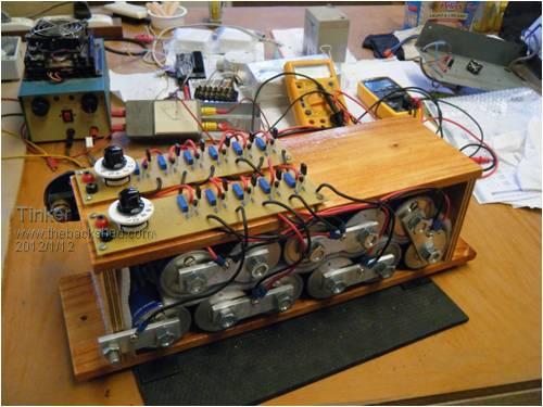
There is a rotary switch on each board that selects an individual capacitor so that its terminal voltage can quickly be checked on a plugged in meter. Each board accommodates 6 identical equalizers but since I only use 11 capacitors in my 24V nominal system one board has only 5. First tests - with my variable power supply - indicates the circuits are working. One shunt transistor got very hot (its cap had the highest terminal voltage and excess was shunted off) so I think I will fit small heatsinks to each transistor. Since my power supply only makes 26.5V max I was wondering why the transistor got hot as 26.5V is way below the max combined cap voltage limit. It turns out there appears to be a faulty TL431 on one board whose associated cap was way undercharged. I will fix that tomorrow, then do some more bench tests and if all is well mount the cap arrangement on the wall above the battery bank. Klaus |
||||
| VK4AYQ Guru Joined: 02/12/2009 Location: AustraliaPosts: 2539 |
Hi Tinker Looks to be a good job, always the odd faulty component in the batch to make life interesting. I like the rotary switch for monitoring, with a cheap digital meter included it would save looking for a multimeter at times. I have ordered some low capacity ones to try so they should be here in a few days 10F should be enough to experiment with. I got into the utube video and very impressive, I wonder how it would go under load though, I guess you will get around to that when other issues are sorted out. All the best Bob Foolin Around |
||||
fillm Guru Joined: 10/02/2007 Location: AustraliaPosts: 730 |
Hi Tinker, Well done and looks like a nice job on the balance boards with the rotary switch. My bank has been going for over 3 mths and definatly maximised the power storage/absorbtion above the voltage that my system holds at 53V , with the solar and wind power surges being captured and not backed off and lost due to the grid inverters not being able to act fast enough . I do feel though that in other applications where there are no requirement Ultra Caps will serve little purpose. I did have a badly out of balance situation on 2 caps of my 25 where they would go down to 1.5V ~ 1.8V over 1 week ,where all the others were quite acceptable, I pulled the balance board out and found the LEDs / diodes were damaged and replaced them . The Led passive balancers seem to be doing an reasonable ok job for this application and it is good to have a direct visual on what is happening and quite easy to see a dim led indicating an out of balance Cap . PhillM ...Oz Wind Engineering..Wind Turbine Kits 500W - 5000W ~ F&P Dual Kits ~ GOE222Blades- Voltage Control Parts ------- Tower kits |
||||
| Tinker Guru Joined: 07/11/2007 Location: AustraliaPosts: 1904 |
Thanks fillm, for the compliments. I am hoping the ultracaps supply the power surges when the two fridge compressors cut in and even the load on the battery bank. Wind power is only at the experimental stage at my place, tracking solar panels are the main power source. Bob no chance to test the caps at starting my car, its a modern diesel motor  . .
BTW, the faulty component turned out to be the shunt transistor. I will definitely fit small heat sinks on each, even though they are rated at 1.5A each (BD140's). The problem was most likely caused by myself trying to adjust the balancers with them connected to the capacitors. This is a frustrating exercise and the adjustment is much easier without any capacitor connected. Just connected 2.8V (via a 0.47 ohm resistor) to each balancer in turn and adjust the pot for 2.6V at the rotary switch selected multimeter terminals. That way each balancer can be adjusted precisely to the same shunting voltage. Now I need to get a bigger transformer for my bench supply so its capable to source 29V DC. I can then test the cap bank on the bench and see if the individual caps equalize once their voltage reaches 2.6V. Klaus |
||||
MrDelanco Senior Member Joined: 12/11/2011 Location: United StatesPosts: 101 |
Nice work looks like we are moving in the right direction here. Regards Robert. MrDelanco:Project Videos It is not only too know what it does but to understand how it does what it does. |
||||
| Tinker Guru Joined: 07/11/2007 Location: AustraliaPosts: 1904 |
My ultracap bank is installed on the wall above the battery bank now. 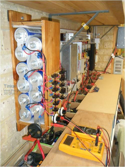
The initial balancing worked rather batter than I expected. Each balancer was first preset to 2.60V. Then I connected the cap bank to my power bench supply set to 29V via a series resistor and watched the voltage at each cap slowly raise. As soon as the first reached 2.6V its associated balancer started to shunt current to the others in the chain. The transistor got quite hot at this stage, just as well that I had fitted small heat sinks to each. But the other caps quickly caught up and the transistors cooled down again. Initially there was as much as 0.3V difference in charge on the capacitors. Once balanced that difference was about 10 milli Volt. 24 hours later they are still all within 30 milli Volt, even though today the battery bank never got full enough to reach the cut in of the balancers. I think this circuit works rather well for my installation. Max battery bank voltage (set by the charge controller) is 29V. This equals 2.636V across each cap if they are balanced. Since the balancing starts at 2.6V there is a max of 36mV that the shunt transistors have to bleed off. These transistors are connected straight across the cap terminals, there is no series resistor. 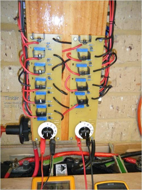
First impressions are the battery bank overnight minimum voltage (caused by the fridge compressor starting up) is now higher. Time will tell what else is changed. Klaus |
||||
| WindyMiller Regular Member Joined: 05/04/2011 Location: United StatesPosts: 62 |
Tinker, That is an impressive setup you got there Mate! I was just wondering if you could show off, or maybe explain some of the other stuff we see on the walls? I always like seeing how others have setup their systems? Helps me get ideas on how to setup my own power station someday soon. Robert |
||||
| larny Guru Joined: 31/10/2011 Location: AustraliaPosts: 346 |
Tinker, As far as I can gather, you have used shunt regulators across each cap to ensure that they all have about the same voltage across them when connected in series. Is this true? My recollection is that all you need is to shunt them with is equal value resistors. The resistor string causes balancing by allowing some charge to by pass some caps so the voltages are approx equal - as set by the voltage divider effect of the resistors. As I guess you know, if there is no balancing, then the voltages depend upon the capacitance of each cap. Since they won't all be equal but they will all have the same charge, then the voltages won't be equal since Q = C*V hence C1*V1 = C2*V2 = C3*V3 etc. Therefore V1/V2 = C2/C1 etc. so V1 can only equal V2 if C1 = C2. Len |
||||
| Tinker Guru Joined: 07/11/2007 Location: AustraliaPosts: 1904 |
Klaus |
||||
| Tinker Guru Joined: 07/11/2007 Location: AustraliaPosts: 1904 |
Thanks for your interest Robert, below are two more views of my RE power plant 
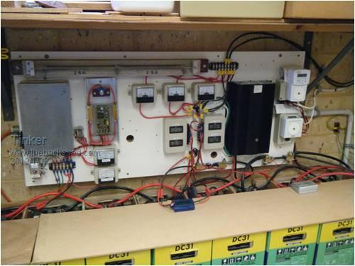
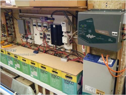
Klaus |
||||
fillm Guru Joined: 10/02/2007 Location: AustraliaPosts: 730 |
Hi Tinker, Yes, a very nice setup tinker , good to see a quality Aus build inverter hanging on the wall . PhillM ...Oz Wind Engineering..Wind Turbine Kits 500W - 5000W ~ F&P Dual Kits ~ GOE222Blades- Voltage Control Parts ------- Tower kits |
||||
| larny Guru Joined: 31/10/2011 Location: AustraliaPosts: 346 |
Klaus, This technique is not suitable for your situation because of the large size capacitors, and as you said, the constant current drain. It is used in Power Supplies when you need a high voltage capacitor that can't be bought for can't be bought at a reasonable price. In that case, the capacitor values are much smaller than in your case and therefore the resistors can be relatively large. A small current drain is of no consequence tsince the power is being supplied from the mains. I mentioned it mainly as a point of interest. Len Here is the basic circuit. 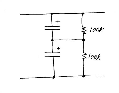
|
||||
| WindyMiller Regular Member Joined: 05/04/2011 Location: United StatesPosts: 62 |
Tinker, Thanks for the additional photos of your setup. I really like the way you have everything so neat up on the wall. Very impressive system in my personal view. Excellent Mate! Robert |
||||