|

|
Forum Index : Electronics : 3 phase winding headache
| Author | Message | ||||
| yahoo2 Guru Joined: 05/04/2011 Location: AustraliaPosts: 1166 |
This has really been doing my head in. Since the conversation about the wiring on Govertical's multi stator generator and this link to 3 phase basics was posted, I have been closely looking at peoples stator builds and wiring on the internet, for signs that people are not winding or wiring one phase in reverse, plus any techniques for testing that it is wired correctly.It has been a pretty fruitless search. I like to be able to visualize how something works in my head, but the combination of the 3 flows of the magnetic flux and the direction of electrons in 3 sets of coils all out of phase is to much for my tiny dysfunctional brain to handle. After looking at the alternator page on wikipedia (they have 2 rotating gif's of the magnetic field vectors that help a bit) and building a pretend 4 pole generator out of cardboard and plastic to help me see where the electricity is going at any one point, I'm still not convinced I have it clear in my head. Wondering if I could measure something on a rotating generator that would clearly show the difference? yahoo I'm confused, no wait... maybe I'm not... |
||||
| Tinker Guru Joined: 07/11/2007 Location: AustraliaPosts: 1904 |
Yahoo, I was in your shoes a while back with the same query. I really should know as I finished an electro mechanics apprenticeship many many years ago but had worked mainly in electronics since until my retirement. Anyway, a real good way to see what's going on is to look at the output on an oscilloscope as you turn the alternator slowly by hand. You'd quickly see the trace peaks have to follow one another at 120 degree intervals and if they do not you'd connected something wrong. Now, 3 channel oscilloscopes are not common but I think these new fangled turn your computer screen into an oscilloscope gadgets might be the go. I have not used one yet BTW. The F&P stators do not seem to have any coil (groups) connected in reverse and they work well. Klaus |
||||
| Greenbelt Guru Joined: 11/01/2009 Location: United StatesPosts: 566 |
Yahoo2 The 3 phase Basics Link is dedicated more to induced magnetic fields than Permanent Magnets , A PM retains is magnetic field polarity while Induced Magnetic fields follow the AC current polarity Like a fast Ocean Wave right around the rotor, The Reluctance of the Iron core ( slow to build a magnetic field or to loose it) is the principle behind the Induction motor.--EDIT: all poles and phases are active at the same time, and each Phase has its own circuit of Series Coils in the stator, also 3 phase is shown as if all phases are on the same conductor this is confusing to many people, 3 phase is really 3 single phases with the frequency peaks timed at 120 Deg. apart or 1/3 circle/cycle. This is why a separate rectifier is needed for each phase, Hooking the phases together before the rectifier would be a short. Note; since I'm making this post I am going elementary on some of this for the Newbies to electricity. END ED. A charged section of the rotor is repulsed by the same magnetic polarity in the Stator before the rotor can loose its Magnetism. A PM Motor or Alt, has the magnet poles reversed and coils are all wound the same way, ------------Cheers, Roe Time has proven that I am blind to the Obvious, some of the above may be True? |
||||
| VK4AYQ Guru Joined: 02/12/2009 Location: AustraliaPosts: 2539 |
HI Yahoo If you open circuit the three phases and turn the alternator by hand you ban tell by the loading into a resistive load in the case of star, or simply connecting the three phases in delta, if out of phase it is hard to turn, In star the out of phase winding will be less loading when turned, With series coils you need to measure the voltage of each coil then the voltage across the coils as you go along the string to be sure the voltages are additive. All the best Bob Foolin Around |
||||
| yahoo2 Guru Joined: 05/04/2011 Location: AustraliaPosts: 1166 |
Roe, this is something I have never seen, all the commercial alternators I have worked on have a rectifier circuit that feeds DC (albeit lumpy sometimes) into the rotating field coils so the polarity of the poles are always the same. I tried a scope on a 12 pole turbine I am repairing but there is no "nice" wave to compare between the phases, it looks ugly. I tried with light bulbs as resistance but the resistance changes as the filament heats and changes the load on the alternator. I cant decide if I am looking at it wrong or the 3 phase basics page is bullsh*t. I understand that while any one wave peaks in the positive direction the other two will be at half strength in the negative so there should be no current flow at the star point at any time perhaps I can use this to play with the windings and watch what happens. That is the point of the original question, I can sometimes feel when I have got it wrong and swap a couple of wires and it is fixed BUT I then have trouble looking at the stator coils and seeing what the orientation actually is and if it matches what I have read. yahoo : thanks fella's, Gotta run, picking some mulberries for Chrissy dinner! I'm confused, no wait... maybe I'm not... |
||||
| yahoo2 Guru Joined: 05/04/2011 Location: AustraliaPosts: 1166 |
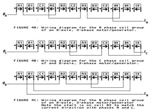
I think I found what I am looking for polyphase motor/generator the "how it works" section explains things how I see it in my head. 
image owner Alan M. Swithenbank http://www.stanford.edu/~hydrobay I'm confused, no wait... maybe I'm not... |
||||
| Greenbelt Guru Joined: 11/01/2009 Location: United StatesPosts: 566 |
yahoo2 Ok The multiphase alternator have many ways to excite the energy producing coils. My previous post was obviously not, Engineering level. I was describing a syncronous 3 Ph. Motor. If you are repairing prime movers then you are working with a zoo of different animals, The DC voltage applied to the Rotor or the stator coils is a variable current that controls the strength of the electromagnets whether they are mounted on the Rotor or stator, it helps to keep the voltage output at a constant level when under high load or light load. Old equipment used a huge wirewound Resistor, (Rheostat) (NICHROME WIRE) to vary the field strength. A PM alt. doesn't have this capability without using other equipment that is very expensive when controlling several KW. three phase basics The subject here is when the rotor has turned 270 degrees the B group is below north pole zero Volts and should have south voltage building. That's why the Lead is reversed. I personally think this is a stupid way to build an alt. surely 9 mags is not going to starve you if you can afford 8 Another note here for beginners: The auto Alt. has a field magnet on the rotor wound axially with an iron end cap on each end and slotted fingers that interlace each other like the fingers on your two hands will. the fingers create alternate pole faces that pass the stator coils and the coils are wired to output 3 phase. the Regulator controls the Load.---Cheers,Roe Time has proven that I am blind to the Obvious, some of the above may be True? |
||||
mac46 Guru Joined: 07/02/2008 Location: United StatesPosts: 412 |
Greetings everyone, I can't resist the fact that I'm in the same spot as yahoo2, and must post this as an additional comment. I'd like to thank everyone for contributing and helping me to come to some understanding of the basic 3-phase motor when used as a generator. I'm a hands on type, and as such, won't be able to grasp this until I have it on the bench. It seems I can read and research for days and even weeks, but won't understand any of it until I have my day in the shop. Regargs, Mac46 I'm just a farmer |
||||
| yahoo2 Guru Joined: 05/04/2011 Location: AustraliaPosts: 1166 |
Looks like there are a couple of errors on Alan Swithenbank's poly-phase generator page. He has written the start of the 3 phase explanation while still thinking about his single phase build. So the reference to 8 magnets and the formula for calculating the number of coils needed is not correct, he is clearly using 16 magnets and 12 coils, equivalent of the bog standard otherpower.com axial flux machine. However the process of creating the diagram to show the current flow in the coil is what I was missing. 
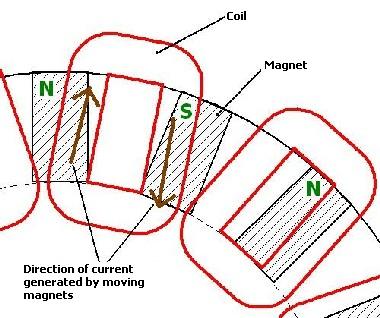
Seems like the key is to draw the coils as in the diagram I posted above(minus the arrows), then looking at the rotor fitted to the stator with a north pole at 12 o'clock at the start of coil A1, draw the arrow to indicate the direction of the current flow in that coil. Then working clockwise around the coils, looking at the magnets over the coils and decide the direction of current flow and draw the directional arrow for each coil into the wiring diagram. This becomes the template for wiring the stator. This is image is how I am looking at the current flow in the coil. 
yahoo images from reuk.co.uk and http://www.stanford.edu/~hydrobay I'm confused, no wait... maybe I'm not... |
||||