
|

|
Forum Index : Electronics : Battery fuse holders
| Author | Message | ||||
| Gizmo Admin Group Joined: 05/06/2004 Location: AustraliaPosts: 5078 |
I made some battery post fuse holders today. I have 4 lead acid batteries connected in parallel, nothing special, powers some garden lights. I do have a big 50 amp maxi-fuse to protect the whole bank, but I really wanted to fuse the batteries individually. As I only draw a few amps, 4 amps max, I decided to use cheap automotive blade fuses. But how to mount them? First up, some spade connectors. I used the type shown on the left, with the basic crimp, its easier to slide off the plastic insulator and they will fit neatly into the big eyelet connectors. 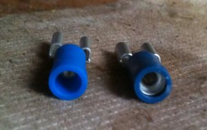
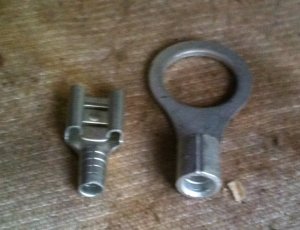
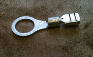
I bent the eyelet crimp at right angles and fitted the spade connector, perfect fit. 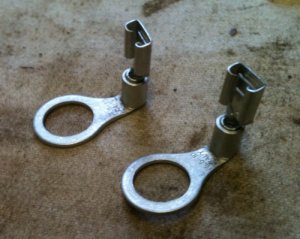
Then soldered them together and fitted some heat shrink. 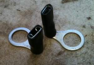
Fused fitted. Marked out a piece of masonite ( 3mm ply wood would work just as well ) and drilled to suit the eyelet spacing. 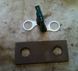
The finished fuse holder mounted on a battery terminal. Cheap and does the job. 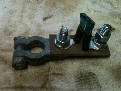
Glenn The best time to plant a tree was twenty years ago, the second best time is right now. JAQ |
||||
| grub Senior Member Joined: 27/11/2007 Location: AustraliaPosts: 169 |
That is very clever. It would never have crossed my mind to come up with a fuse holder like that, I would have just bought one. I will keep that idea tucked away in my mind. |
||||
| VK4AYQ Guru Joined: 02/12/2009 Location: AustraliaPosts: 2539 |
Hi Glenn Good idea, thats innovation, on the same theme I have made fuse holders like that using double sided fiber glass pc board by drilling a hole to take the spade terminal and soldering to both sides, with a cut in the copper both sides of course. Doing it this way it is possible to string a series of fuses on the one piece of board to the one active terminal. I have tested it to 30 amps and the board will take it OK. It is a good idea to tin the board for corrosion and to carry a bit more amps, then a coat of clear estapol or similar, A led and series resistor across each fuse ads a blown fuse indicator without having to pull them out to test. All the best Bob Foolin Around |
||||
| Xmaswiz Regular Member Joined: 14/04/2011 Location: United StatesPosts: 69 |
I'll be using both ideas on my little project, thanks for posting, it sure helps to find all the great ideas already there, save some of my poor little brain cells from burning out trying to figure out what works!!!  Santa Maria, CA. Noel |
||||
| LightLED Newbie Joined: 14/02/2011 Location: AustraliaPosts: 9 |
Very nice. Bookmarked for future reference. Light upgrades Life with LED Light Bulbs. |
||||
| norcold Guru Joined: 06/02/2011 Location: AustraliaPosts: 670 |
Love it Glenn, many thanks for sharing that. Will be a few getting made around my place in the future. We come from the land downunder. Vic |
||||