
|

|
Forum Index : Electronics : Doing it the hard way
| Author | Message | ||||
oztules Guru Joined: 26/07/2007 Location: AustraliaPosts: 1686 |
Sometimes people expect you to do what appears to be simple to them, but is a nightmare to me. If you can load batteries into a torch, you obviously know all about electronics and can fix anything with a switch on it......where do they get these ideas. I'm posting this, just to give some hope to older fogies like me who have done limited electronic trickery in their time as a hobby..... and get tired of all the new fangdangled electronic thinggies... and how they are built, and how are you gonna fix em when they fail.... A sorry looking local looked me up, and asked if I would look at his computer screen. I figured it was a CRT type, and accepted the challenge. Yes I said, figuring if it wasn't the EHT transformer, I had a better than fair chance of fixing it. The owner and the screen dutifully turned up and it turned out to be a very new looking 20 odd inch LCD device. I went cold to the core... cursed things, I bet they use those hard to see and even harder to get hold of surface mount bits and pieces. I was about to tell him to take it to the tip as I didn't feel too confident about it at all, but before I could get it out, he couldn't help but tell me that.... so and so said I could do it no problems etc. etc. I was cornered by local legend and vanity.... egad. Well, I shuffled off to the shed with it, mumbling things about Gordon and his proclavity for surface mount things... and anyone else who encouraged them.... I figured that at least the power supply would be through hole, and probably the fault would be there, and barring exotic components I didn't have, we'd still carry the flag.... Most of the satellite decoders, dvd players etc so far have through hole power supplies, and surface mount after that....we live in hope. It took ten minutes to find out how to open the damn thing. What ever happened to a few well placed screws. It was all very cunning... but with patience and good management (and a few swift thumps), it came apart. I didn't take any photo's at this stage, as I didn't think it would ever go again. The blown fuse, and black smoke marks across the board almost encouraged me to put the cover back on and call the owner..... but I just couldn't help but look in wonder at all the little bits and pieces too small to see almost, and marvel at how they must do these things. Well, we'd gone this far, so how does it work anyway. Popping off the screen and wiring harness to it, we find this...... the screen carries a mountain of very intricate whoop arse looking gear, and I ain't ever tackling that. 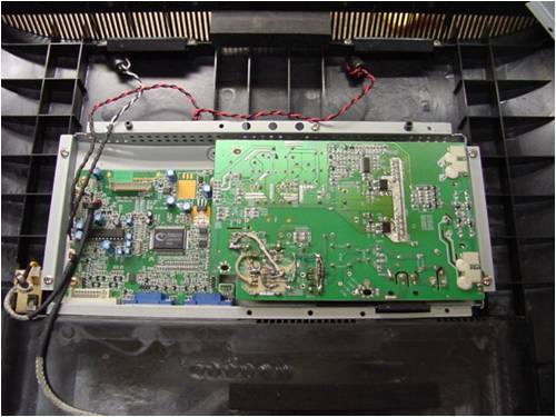
Actually, the bottom of one of those boards has been butchered, as this is after the ordeal, not before.... My heart sank, as I didn't recognize any of those little bits as normal stuff. I pulled off the top board, and cheered up some.... there was at least some through hole bits to look at: 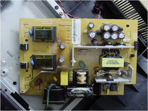
You can see that there has been a fair amount of butchery there too... no before shots I'm afraid. The black marks have been cleaned up some. The Fet was blown up, the fuse was blown, and ...... where was the PWM chip..... The PWM chip was one of those cursed surface mount things...yes, on the hard to see side of the board and surprise surprise, 320v going through one of them just leaves a smudge and some leads and burnt plastic. Things looked grim about now, and I vowed to look at it some time later, and tipped all the bits back into the rear frame and let it sit for a few days... and then some. Some days later, I decided to trace out the tracks away from the 8 pin pwm site, to see if I could guess what the part may have been. The 320v from the rectifier went straight to the chip.. pin 8 in fact. This told me that the chip was one of those "greenie" chips, which used the HV to bootstrap direct, and then turn it off and run from the tertiary field, rectified and then used as vcc... pin 6?. Output was pin 5, ground pin4 and feedback pin2.... etc. This narrowed it down. The second green pwm chip I researched was an ld7575... and it matched pin for pin. I was shattered, I couldn't track one down anywhere.... I needed a plan B. Looking at the data sheet for the 7575, we find a typical simple flyback circuit looks like this : 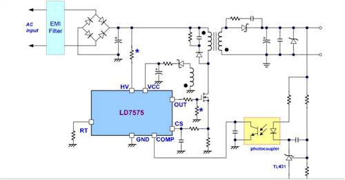
I did another quick trace, and whilst it wasn't the same at all, it sported an opto isolator, transformer with tertiary winding... and well.....that was good enough for me. I grabbed the trusty 3842's out of the box, and proceeded to graft it onto the board... this was the tricky bit. Their entire PWM was built on the surface mount side, and 20 odd components used less room than a postage stamp.... what to do. The big smoothing capacitor took up a lot of real estate on the top side of the board, so I resolved to use this space, and put the capacitor elsewhere.... anywhere..and a few (what I felt) unnecessary compoments were turfed out all together. It now looks like this 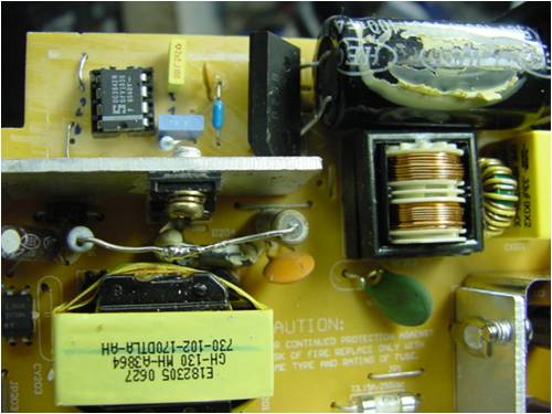
You can see the capacitor was prized off the board and repositioned (where some other stuff used to be), the bridge was moved back a bit, and the 3842 through holed into a socket... (not very confident are we??). A few more holes and a few bridging wires, and we have half of it built. On the other side it looks just as woeful: 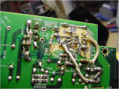
I scratched all the surface mount stuff off the board with a razor blade, and scratched all the tracks off as well. With some filthy soldering and slapping the bits on, I was finished. I replaced the Fet from out of a computer monitor from the tip, and last but not least, I wired up a rudimentry bootstrap circuit (80k resistor and 18v zener)......The bootstrap is the two messy looking resistors between the transformer and the fet. 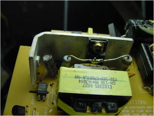
After this, the tertiary should take over..... and it didn't. The 3842 I had (gotten cheaply from Rockby) didn't turn on until 16v... and the tertiary winding was only 12v...dammit... 16v wins, and the tertiary doesn't get a look in. I'll worry about that later, the bootstrap will carry it until we find out if the rest of the thing works. It was modeled around this circuit here: 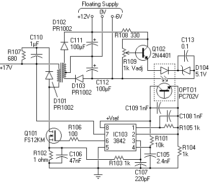
Obviously were running it at 320v not 17v... but close enough... Well it was time for the quick check around the board to see if all was well.. 3 electro's were down from 1000uf to about 50uf. This is what appears to have o/loaded the fet which then blew everything up.replaced these and moved on to the 2000v screen supply PWM. At least this although surface mount, used a surface mount tl494... home territory. I used a 14v supply to mimic it's input voltage. The oscilloscope showed the oscillator was functional, and by driving the dead time pin down, the 2000v hissed into life for a few seconds. I tracked down who was turning me off, and bypassed that (the computer on the other board controls this chip for brightness, sleep etc.)... satisfied with this.... it was time to switch on.... and I was greeted with this..... 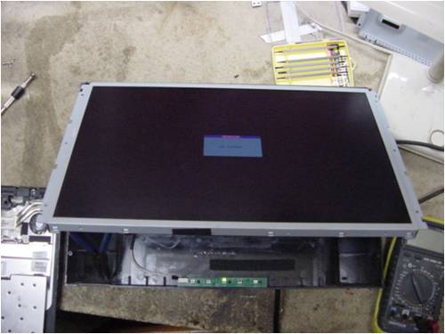
Feeling pretty smart about now.... and then it went blank...panic sets in, I go over it all , and all seems fine. Switch it on, and it works and stops again. These smart damn machines, I had forgotten to give it some video drive, so it switched itself off after 20 seconds.... nothing wrong at all perhaps. I had found an old laptop at the tip.... 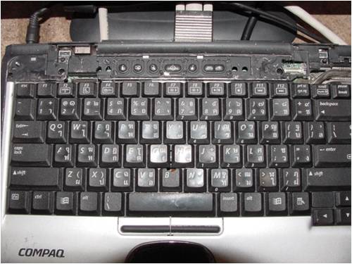
After fixing it up (idle Fet), and tossing aside the screen/lid, and cleaning it up, loaded up some software (Linux Ultimate2) and tried again.... this time it was all different. 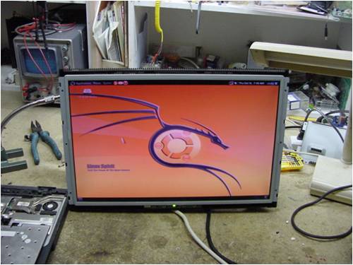
and for more complex stuff like this: 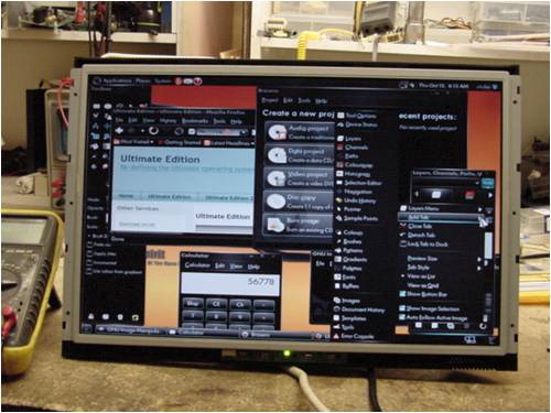
So, there is hope for those Neanderthals out there, who like me rue the passing of valves, and then sort of rue the passing of transistors.... and are less than impressed about the surface mount stuff.... if you stick to your guns, and smash out some extra space... we can still fix somethings. But for how much longer 
............oztules Gizmo, Feel free to kill it off if you think it is too far off topic. I think I did it for therapy  ... and I know Gordon loves his surface mounts ... and I know Gordon loves his surface mounts 
Kill it?! This stuff is gold! Seriously, these sorts of posts are great, thanks for posting it Oz. Glenn Village idiot...or... just another hack out of his depth |
||||
| Dinges Senior Member Joined: 04/01/2008 Location: AlbaniaPosts: 510 |
You know how occasionally when driving you see a bit of roadkill lying on the road in the distance? And as you get nearer you think to yourself that you shouldn't watch all that blood and gore? And that you then decide not to watch it, but will look straight ahead ignoring it? And that when you are getting really close to it you can't help but watch anyway? And how, as you are watching, you already regret doing so? That's how I felt reading this post.... Some of the pictures in this story will be etched into my mind till my dying days. The stuff of which nightmares are made - the kind where you wake up in the middle of the night, soaked in sweat, screaming for mercy. There should be laws against such butchery. Once convicted, said persons should be forbidden to ever own a soldering iron again, or come within a 50m radius of one, on pain of banishment to a remote settlement - Van Diemensland or one of its islets perhaps? Peter. (dreads to think what mischief Oztules could achieve with a crystal, a PL504 and a transformer) |
||||
oztules Guru Joined: 26/07/2007 Location: AustraliaPosts: 1686 |
Dinges..... do you mean somewhere like this? 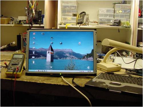
I thought it would be tough for you to read all the way through it without feeling nauseous..... does this mean you don't trust me to work on your plane? 
..........oztules Village idiot...or... just another hack out of his depth |
||||
| Barry T Coles Senior Member Joined: 30/07/2009 Location: AustraliaPosts: 109 |
If your a Neanderthal then I still a microbe, after reading about a quarter of that I resolved that I would have just bin jobed the piece of junk. Good onya for sticking with it youv'e got more patience than I have. Cheers Barry I need to learn from the mistakes of others. I dont have the time to make them all myself. |
||||
fillm Guru Joined: 10/02/2007 Location: AustraliaPosts: 730 |
Doc Oz , you really should have a go at building a "flux capacitor " for the EV .. The whole thing is way over my head , but totaly enjoyed reading about it .. PhillM ...Oz Wind Engineering..Wind Turbine Kits 500W - 5000W ~ F&P Dual Kits ~ GOE222Blades- Voltage Control Parts ------- Tower kits |
||||
| Smart Drives Senior Member Joined: 06/07/2009 Location: AustraliaPosts: 115 |
If Dinges thinks that is butchery i better not post my attempt at Downwinds (awesome) encapsulated resistor. I would be hung drawn and quartered... But with 2 stove top elements i did get 8amps at 54 volts, it looks like a dogs breakfast but it works. Cam. All smart drive parts sold Custom built turbine parts on Multicam flatbed CNC Router |
||||
| GWatPE Senior Member Joined: 01/09/2006 Location: AustraliaPosts: 2127 |
Hi oztules, You have found another way to skin a cat. Most problems occur in the power supply dept. I think the engineers that design these things could spend some more time with the power supplies. Too many consumer appliances end up at the tip with a faulty component in a power supply. It looks like you have some more browny points with this repair. My repair of a similar type LCD was relatively trivial. Had a plugpac power supply, so only needed to replace the 5V switchmode controller witrh an equivalent dogs breakfast. Well done. Were the covers able to go back and keep the mains side safe? Gordon. PS pity the normal cap replacement fix was not an option. become more energy aware |
||||
oztules Guru Joined: 26/07/2007 Location: AustraliaPosts: 1686 |
Yes Gordon, The plastic facia is all back on, and Dinges would never know I was there. All the consumer appliances will be at the tip... and nearly all will have failed capacitors. Some with blown up fets, but most with just tired caps that stop the PWM from getting up past critical turn on... and so pulse erratically, but never actually run. I think the engineers are to blame in as much as the caps are run pretty hard.... but maybe the purchasing department carries some of the blame. The cheapest part wins the contract. If they bought better caps, maybe they'd last more than a year or two. I was surprised these things have such high voltages. When I kicked off the second PWM that drives the screen, it drew an arc over 5mm without a problem... scary stuff. I just wonder at how you enjoy playing with those iddy biddy toy components.... but they do a fine job I must admit. Phill, I'm just a bushranger. I barely understand these things either. This was my first real look at an LCD screen. The stuff built onto the screen panel itself is pretty space age looking, and out of my league. The driver /computer board is pretty much off limits as well. It uses chips you will never get and parts you can't hardly see.... That leaves the power supply part, and even there they have made it difficult with surface mount on one side and through hole on the other.... but it is understandable.... the rest is just voodoo proprietary stuff. I doubt the manufacturer could fix any of the other boards.... so I don't feel bad about it. Barry, I'm just a stubborn varmit, and Cam, it only has to work...... it's not our fault that Peter has decent standards... like Phil, and Gordon.... and.....gee perhaps we are alone...... ...oztules Village idiot...or... just another hack out of his depth |
||||
Downwind Guru Joined: 09/09/2009 Location: AustraliaPosts: 2333 |
oztules Fantastic job. 
I really enjoyed reading your post. It was far better entertainment than the "serviceman's log" in a Silicon chip magazine. There should be more of it. Did you find a use for the encapsulated resistor?? I would be interested to see a pic of what you ended up with ( email me one ) Sounds like you started with a poor element choice for the challenge. Your posting was a pleasant change from looking at the inside of motors and magnets. The flux capacitor sounds like a challenge. 
Pete. Sometimes it just works |
||||
| Dinges Senior Member Joined: 04/01/2008 Location: AlbaniaPosts: 510 |
[quote=Oztules]I think the engineers are to blame in as much as the caps are run pretty hard.... but maybe the purchasing department carries some of the blame. The cheapest part wins the contract. If they bought better caps, maybe they'd last more than a year or two.[/quote] Oztules, as long as the equipment keeps working throughout the warranty period I doubt the manufacturer will care about this. And fact is most consumers don't care either, judging by their buying behaviour. Most electrolytics are rated for about 8000 hours (at elevated temperatures). Fully agree with your statements about the electrolytic caps; they are the single most unreliable component that I know of. As far as repairability of modern electronics goes... a friend showed me his new iPod the other day. About the size of two credit cards stacked on top of eachother. There is a battery too inside there somewhere. Oh, and a camera. Amazing. In my short lifespan I've experienced the final days of valves too. I dread to think of what electronics will look like in another 35 years. Strange you couldn't find the LD7575. Just had a look at the manufacturer's site and the IC is still in production. Could've tried to request a sample. Also noticed the IC is for sale here in Europe for E.5,50. BTW, very impressive job on the reverse engineering. Think I'd have given up much sooner than you. Or, more likely, if the power supply puts out standard voltages, I'd have installed a powerjack in the casing and used an external custom powersupply; either a (modified) PC PSU, or perhaps even a linear power supply of sufficient oomph. 'Customer' would end up with an extra box under his desk (PSU), but at least the monitor would work again. Always several ways to skin a cat. Last time I fixed a junked LCD monitor (a very nice NEC), it was an intermittent problem on the fluorescent driver board. Loose SMD resistor, easy to track with a bit of freeze spray. Resoldered and is working solidly now for about 3 years again here on my desk. You do realize that you've just set the bar a little higher again for yourself? Islanders are by now even more convinced that there is *nothing* the Oztules can't fix. Will get increasingly harder to live up to that sainthood.... Peter. BTW - last week I visited a friend. He had a 6 cylinder 1920s Italian star rotary aircraft engine in his shop for some small work. *Very* impressive gadget! Is of someone else who's now building a Pietenpol. |
||||
oztules Guru Joined: 26/07/2007 Location: AustraliaPosts: 1686 |
Yes, for the consumer to keep up with the fads, I guess if it lasts a few months it is enough... I found the 7575 in Bulgaria and decided to try to get it, but the minimum purchase on overseas (outside Europe) made it a joke. Same in America. If you can't get it on Ebay internationally, or local, you can probably buy a new screen for the price of the international shipment. I ended up with a 1000 D92 rectifiers this way, and 500 pwm chips single ended, 300 double ended...etc. I also didn't know if the replacement of this part would give it life.... or just money down the drain... To be honest, I didn't expect to be able to fix it , so that is why it was so rough... quick "wonder if this will work" thing...not expecting 100% success. "You do realize that you've just set the bar a little higher again for yourself? Islanders are by now even more convinced that there is *nothing* the Oztules can't fix. Will get increasingly harder to live up to that sainthood...."....... your right..... ooops. Those Pietenpols look a popular pastime. Plenty of video's of them and their masters on the web I see. ........oztules Village idiot...or... just another hack out of his depth |
||||
| Dinges Senior Member Joined: 04/01/2008 Location: AlbaniaPosts: 510 |
Oztules, I only now realized something: that big glob of adhesive on the electrolytic capacitor..... Looking at the board, I don't see anything else to which they could've bonded that capacitor than to the heatsink of the switcher FET. Please, *please* tell me that they didn't do that.... If there's one thing electrolytic capacitors can't stand it's heat. Expected life of an electrolytic cap decreases very rapidly with relatively small increase of temperature. Providing a thermal bridge between such a capacitor and a warm (hot?) heatsink would not be a very smart thing to do. Peter. Edit: dumb of me - that's the replacement capacitor, not the defect one. Scratch previous remark. |
||||
oztules Guru Joined: 26/07/2007 Location: AustraliaPosts: 1686 |
Dinges, That is the original cap. It was glued to the board. It is only a filter cap on the HV side..... but I needed it's space ... so flipped it. The failed ones were on th LV side. (25v not 320v). 1000uf@320v would be a touch bigger me thinks.. .........oztules Village idiot...or... just another hack out of his depth |
||||
SparWeb Senior Member Joined: 17/04/2008 Location: CanadaPosts: 196 |
Ah, well, at least now I understand why there's all that goop on the cap. I thought it was dead one, too. Thanks, Oz, for the story. Most people would not believe that looking at the other side of a TV would be more entertaining than the front side of it. Steven T. Fahey |
||||