| |
  Page 2 of 2 Page 2 of 2 |
| Author |
Message |
liqud

Newbie

Joined: 11/08/2009
Location: United StatesPosts: 22 |
| Posted: 07:55pm 05 Sep 2009 |
 Copy link to clipboard Copy link to clipboard |
 Print this post |
|
what would be the correct rectifier or diode size for 1kw 12vdc optimal ax fx 3phs to build or at least the math to figure this out on my own i would prefer to be able to change out the rectifier with tabs but i was looking at 100v 50v rectifiers (MP501W-BPMS-ND)but how does that translate into diode sizing. im kinda lost but i kinda have a good idea of what im doing. thanks guysEdited by liqud 2009-09-07
Shawn C
Real power is not given its made... |
| |
GWatPE

Senior Member

Joined: 01/09/2006
Location: AustraliaPosts: 2127 |
| Posted: 11:42pm 05 Sep 2009 |
 Copy link to clipboard Copy link to clipboard |
 Print this post |
|
Hi AMACK,
There are no component values on the schematic. I assume you know how to connect a bridge rectifier, and you know what a capacitor is as well. The pic is a wiring diag, of how to connect the components together to make a 3phase AC capacitor voltage doubler. As long as you can see the connecting wire placements. I am using an old laptop and the pic comes up OK.
Gordon.
become more energy aware |
| |
AMACK

Senior Member

Joined: 31/05/2009
Location: AustraliaPosts: 184 |
| Posted: 10:01am 07 Sep 2009 |
 Copy link to clipboard Copy link to clipboard |
 Print this post |
|
Gordon, Yes I do know what a Cap is and how to connect are bridge rectifier. The Image was not the point of the post the web site data was. I had a look at the site and it was quite good, I was just trying to inform other of it if they had not already found it.
Andy.
*Note to self
1. Make it thick
2.Make it heavy.
3.Make it stronger than it should be.
4. Don't rush the first job as the second job will cost more and take mor |
| |
GWatPE

Senior Member

Joined: 01/09/2006
Location: AustraliaPosts: 2127 |
| Posted: 11:36pm 07 Sep 2009 |
 Copy link to clipboard Copy link to clipboard |
 Print this post |
|
Hi AMACK,
If you wanted to mention the web site reference, then by all means. OK.
Placing a pic of a series capacitor charge pump, as an example on a windmill forum suggests that this is the way to go for loading a windmill. You did not actually say this, but pictures, even if inappropriate stick in readers minds.
Hi Liqud,
The power handling requirement of a 3phase Capacitor Voltage doubler for a 1kW AxFx mill would be around 100W. You could use 1000uF 160VDC rated caps in a back to back arrangement, [12Caps] with 4 x 10A 100V bridge rectifiers. This would approximately halve the mill cutin rpm. I would use multiple 470uF caps, and have a few spare sets, to allow for unknown blades performance. Too much cap, and the mill rotor can be stalled, and too little results in not much benefit.
You could make 3 full doublers, and add them in to see the best result.
Don't try the series arrangement as shown above, as U will waste your time.
BTW, There have not been any examples of published 3phase parallel type Capacitor Voltage multipliers on this forum, so I guess my design is it. The arrangements are not complicated, but I will not calculate sizings for everyone, as there are too many external variables. A bit of T&E is needed.
Gordon.
become more energy aware |
| |
liqud

Newbie

Joined: 11/08/2009
Location: United StatesPosts: 22 |
| Posted: 12:14am 08 Sep 2009 |
 Copy link to clipboard Copy link to clipboard |
 Print this post |
|
thank you very much i just need a practical design to work with. i have a board designed but the foot prints were way off. i understand u cant do this everytime, and i wholly appreciate your time and thank you for it. I will post my designs and make it usable for all and i will push to make other designs for a host of other ax fx setups. i believe this is crucial in increasing the efficiancy of any wind generator. I will do my best to offer something of use to all people on this site. once again thanks gordon. 
Shawn C
Real power is not given its made... |
| |
liqud

Newbie

Joined: 11/08/2009
Location: United StatesPosts: 22 |
| Posted: 09:42pm 27 Sep 2009 |
 Copy link to clipboard Copy link to clipboard |
 Print this post |
|
Ok I have a some components picked out SLPX471M160C1P3 for the caps they are pretty big and i have the GBU10/15/25 g series rectifiers picked out. actually I have the 25a full wave bridge rectifiers from radio shack for the mock up can someone give me a confirmation that these are usable and correct. I will have a picture of bank boards to ad to one another pics will be up shortly
Shawn C
Real power is not given its made... |
| |
liqud

Newbie

Joined: 11/08/2009
Location: United StatesPosts: 22 |
| Posted: 10:25pm 27 Sep 2009 |
 Copy link to clipboard Copy link to clipboard |
 Print this post |
|
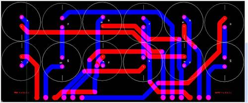
ok here it is just a little something i think its alright
Shawn C
Real power is not given its made... |
| |
GWatPE

Senior Member

Joined: 01/09/2006
Location: AustraliaPosts: 2127 |
| Posted: 05:04am 28 Sep 2009 |
 Copy link to clipboard Copy link to clipboard |
 Print this post |
|
Hi Liqud,
I just use hot melt glue and soldered wire links. The camponents are big enough to just glue and hard wire together. I reckon a PCB just makes it harder.
Gordon.
become more energy aware |
| |
KarlJ

Guru

Joined: 19/05/2008
Location: AustraliaPosts: 1178 |
| Posted: 12:27pm 09 Nov 2009 |
 Copy link to clipboard Copy link to clipboard |
 Print this post |
|
I know its been a while on this thread but I read all of the cap threads and these
SLPX471M160C1P3 that you picked out may not have sufficient voltage rating.
I think the recommended is 400V+
Luck favours the well prepared |
| |
GWatPE

Senior Member

Joined: 01/09/2006
Location: AustraliaPosts: 2127 |
| Posted: 01:11pm 09 Nov 2009 |
 Copy link to clipboard Copy link to clipboard |
 Print this post |
|
Hi Liqud,
On the PCB art work above. Did You manually place the tracks, or did you use an auto router?
With high voltage designs > 20V, it is good practice to use the component lead spacing as a guide to distance required between power carrying tracks.
A small build up of dust and some moisture, and arcing will soon turn the PCB to a charred useless item.
Gordon.
become more energy aware |
| |
liqud

Newbie

Joined: 11/08/2009
Location: United StatesPosts: 22 |
| Posted: 02:12pm 09 Nov 2009 |
 Copy link to clipboard Copy link to clipboard |
 Print this post |
|
gordon:
yes i have all but abandoned the board idea the hot glue with an enclosure would seem more suitable to the elements. And wire leads to out of the enclosure would be fine.
yes the traces are auto routed for the most part. i think the minimum it will route close together is 6mil but i planned on putting a silk screen layer. And I could easily put some space between those. I will probably do both if i end up using this design in the future. my idea is to be able to add theses in series with clip connects. none the less ill follow through with this design and get it made eventually
karl:
I got these caps picked out per the 400v recommended rating. LGU2G471MELC but im gonna keep looking cause thats too rich for my blood.
thanks for the input guys
Shawn C
Real power is not given its made... |
| |
| |
  Page 2 of 2 Page 2 of 2 |

