|

|
Forum Index : Electronics : Permanent mag alternator
| Author | Message | ||||
| mutzy Newbie Joined: 30/07/2009 Location: United StatesPosts: 4 |
I am brand new to both this board but am interested in windpower and trying to make a permanent magnet alternator from a car alternator. I removed the rotor and replaced with three permanent mags all with same polarity. When tested on lathe with multimeter doesn't seem to be working. Any suggestions on what I've done wrong or other things to try? I've only tried at very low rpm to this point. Thanks!! |
||||
| Gizmo Admin Group Joined: 05/06/2004 Location: AustraliaPosts: 5078 |
Hi Mutzy Its not a good configuration your've gone for there, but it should still make something. How were you measuring the output? Did you use a multimeter across two of the 3 wires, and was your multimeter set to AC volts? Do you still have the original armature, and if you do, how many poles ( fingers ) did it have? Half the fingers will be coming from one end of the armature, and half from the other end. To make you alternator work the best, you should use the same number of magnets as there were poles on the original armature. Glenn The best time to plant a tree was twenty years ago, the second best time is right now. JAQ |
||||
| Greenbelt Guru Joined: 11/01/2009 Location: United StatesPosts: 566 |
Time has proven that I am blind to the Obvious, some of the above may be True? |
||||
| mutzy Newbie Joined: 30/07/2009 Location: United StatesPosts: 4 |
I appreciate the input greatly and you all have giving me some direction to pursue. Thanks again!!! |
||||
| mutzy Newbie Joined: 30/07/2009 Location: United StatesPosts: 4 |
I looked at the rotor that came out of the original alternator and it has a total of 14 poles. The size(width & thickness) of magnets I was using will not allow for spacing of 14 around the circumference and still fit in the original stator. Is it OK to drop 1 or 2 magnets out and go with 12 or 13 instead? Also if I only drop 1 out I would end up with two adjacent mags of same polarity but would provide the most allowable number of magnets. I guess I'm a little confused on the polarity & significance of it. I've seen some very small generators (science project) that make poles all the sameLink to example (pg 11 & 12). What is the difference between using same poles vs alternating poles? Thanks!! |
||||
oztules Guru Joined: 26/07/2007 Location: AustraliaPosts: 1686 |
"What is the difference between using same poles vs alternating poles? " None...ish When we use 4 same poles as in your reference, we are actually using 8 alternating poles. The 4 gaps between the 4 north poles, become "phantom" south poles. They behave exactly like a south pole between each north pole. This technique is used extensively in 4 pole 3 phase induction motors. It allows the use of half the no. of coil groups, which frees up lots of space and end turn resistance. This answers your second question you have forming in your head.... yes seven magnets will do the job. The magnets need only be the width of three stator teeth... no more. They must all have the N or S pole facing outwards.... makes no difference which way you choose... so long as they are all the same orientation. The intermediate gaps will become the phantom other poles...... and it should behave like a 14 pole rotor. (You'd get more power with 14 magnets) ......oztules Village idiot...or... just another hack out of his depth |
||||
| Dinges Senior Member Joined: 04/01/2008 Location: AlbaniaPosts: 510 |
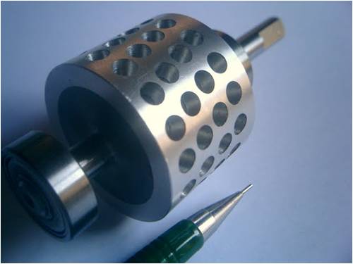
There are various ways to convert your car alternator to a generator. Myself, I would have just treated it like any other motorconversion, made a new rotor and installed magnets on that: 
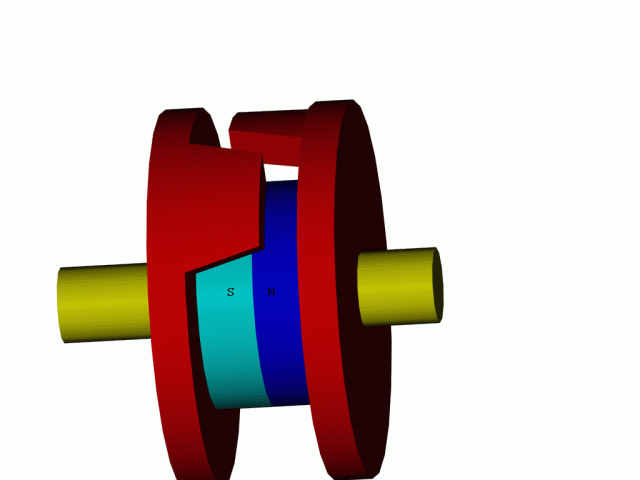
If you have a 14-pole stator (as you apparently have) I would have turned it into a 14 pole rotor. That's the normal procedure. It would require a little bit of machining and access to properly sized magnets. You'd also have to take countermeasures to prevent the rotor from cogging (by skewing the magnets on the rotor, or skewing the stator and rewind). Another solution would be to install one big, round magnet (with hole in it so the shaft would fit through); see sketch below. I've only drawn two pole fingers for clarity. The red rotor plates will guide the magnetic field to the fingers, which in turn will project it to the stator. Just as in the original situation, except now we're using a permanent magnet as opposed to an electromagnet: 
The downside is that some (much?) of the flux will be shorted by the shaft. If you'd not want that, you'd have to machine a new shaft out of a non-magnetic material as for example (austenitic) stainless steel. You'd also need to find a suitably sized magnet (shouldn't be too hard, given the enormous choice in dimensions for magnets that are nowadays available) Assuming that, by using permanent magnets, you can get the same flux densities as the old electromagnetic rotor, the stator would probably also need a rewind if you want the generator (more correctly: alternator, as it produces alternating current) to start producing power at reasonable RPMs (in the 100s of RPM range, as opposed to the previous 1000s of RPM needed as car alternator) To me it seems like a lot of effort for a limited result. Nevertheless, converting car alternators into RE generators is technically perfectly doable. Takes a bit of work, some machining and suitable magnets. Whether it's a worthwhile endeavour? Not for me, but your situation may be different. Peter. |
||||
| mutzy Newbie Joined: 30/07/2009 Location: United StatesPosts: 4 |
Thank you all for the input and direction. I realize this is probably pretty basic stuff for you but appreciate you taking the time to explain this for me. Thanks again!!! |
||||