|

|
Forum Index : Windmills : experimental blade profile
| Author | Message | ||||
| Saaremaa Newbie Joined: 10/12/2005 Location: AustraliaPosts: 13 |
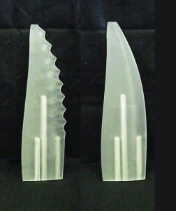
Here is a link to an interesting .pdf file on fluid dynamics. http://www.appliedfluids.com/UUST01.pdf It outlines the use of wavy bumps (tubercules) in the leading edge of an airfoil shape to both decrease drag and increase lift of the airfoil in a fluid. I am guessing but since air is a fluid - the same principles might well apply. The difficulty in making a set of test blades would lie in actually cutting a number of blades with identical bumps along the leading edge. (hint: It would take a CNC router to do it accurately) |
||||
| makourain Senior Member Joined: 19/04/2006 Location: Posts: 111 |
[quote](hint: It would take a CNC router to do it accurately)[/quote] what does the CNC stand for? |
||||
| Gizmo Admin Group Joined: 05/06/2004 Location: AustraliaPosts: 5078 |
Golf balls! They have dimples to reduce air resistance. CNC = Computer Numeric Control. Glenn The best time to plant a tree was twenty years ago, the second best time is right now. JAQ |
||||
| Saaremaa Newbie Joined: 10/12/2005 Location: AustraliaPosts: 13 |
It's not so much small dimples that matter in this case - but larger bumps or just a scalloping of the leading edge. 
I think that if it gives 5% to 10% better performance - on a big blade that is a substantial difference in output over time. here's some more on the same subject: http://www.sciencedaily.com/releases/2004/05/040512044455.ht m http://www.dukenews.duke.edu/2004/05/design_0504.html |
||||