
|

|
Forum Index : PCB Manufacturing : Development/Prototyping
| Author | Message | ||||
| Phil23 Guru Joined: 27/03/2016 Location: AustraliaPosts: 1664 |
Wondering what the board designers here think of the concept of an expansion or prototype board for some of the newer MM's. Many of us develop our projects to their completed stage on Prototyping or strip board etc. It would be nice to have something that mates to some of the above Micromites & possibly also a SnadPic. Mostly external component counts are small, and then there's just there's requirements for connecting the external devices. I think it would be a huge advance for the users that can't design their own boards, which in many cases are just one off projects anyway. Food for thought? Cheers Phil. |
||||
bigmik Guru Joined: 20/06/2011 Location: AustraliaPosts: 2914 |
Hi Phil, All, Please empty your mail box I cant send messages as it is full. I have taken a look at your request and come up with this idea. 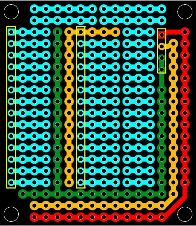
Note the GREEN is GND the ORANGE is 3v3 the RED is 5v the yellow boxes show where female header will mount on the underside of the board to connect with MuP2 or MuP3. The 3v3 appears to be split in 2 but in fact they will connect once plugged into MuP. I have never used this style of prototyping before as I have always used the `sea of holes' type but I can see some merit in it. I am interested in anyone's feed back on this. I will be uploading the GERBERs and DEX project file (the schematic is horrible as I didnt use it except to bring `parts' in I then linked with lines (not tracks) but at least it will be editable if anyone wants them. The board is the EXACT same size as MuP and the mounting holes will align with MuP3 (not MuP2 unfortunately) Kind Regards, Mick Mick's uMite Stuff can be found >>> HERE (Kindly hosted by Dontronics) <<< |
||||
Grogster Admin Group Joined: 31/12/2012 Location: New ZealandPosts: 9303 |
Confirming I also got your PM, and I will reply to you there - now you have cleaned out your mailbox.  Smoke makes things work. When the smoke gets out, it stops! |
||||
bigmik Guru Joined: 20/06/2011 Location: AustraliaPosts: 2914 |
Hi All, No feed back at all but I can see that there is no way to fit an IC in DIP foot print without cutting tracks.. I am not sure how best to overcome that unless I remove the 3v3 and GND going vertical between the PIC chip pins. Stay tuned Kind Regards, Mick Mick's uMite Stuff can be found >>> HERE (Kindly hosted by Dontronics) <<< |
||||
| Phil23 Guru Joined: 27/03/2016 Location: AustraliaPosts: 1664 |
Hi Mick Finally catching up on what I've overlooked. That design looks pretty useful. Or of the office so will have a better look when i return. Not a fan of messages from my phone. Phil |
||||
| Phil23 Guru Joined: 27/03/2016 Location: AustraliaPosts: 1664 |
It will probably make more sense to me when i can look at the mup again. Cheers. |
||||
bigmik Guru Joined: 20/06/2011 Location: AustraliaPosts: 2914 |
Hi Phil, All, I have done some changes (all is a compromise of course) 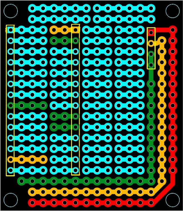
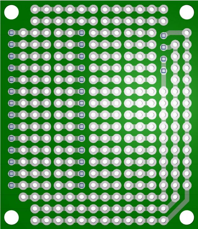
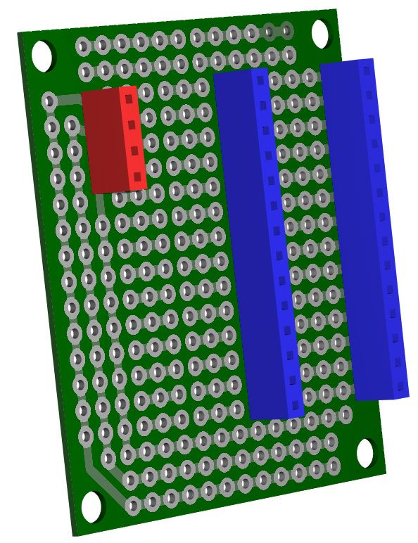
The bottom view shows the 3 female headers (colour matched to the relevant MuP headers) as they would plug into MuP 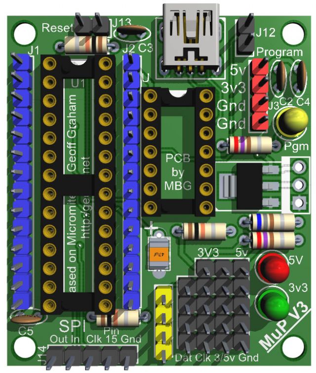
Kind Regards, Mick Mick's uMite Stuff can be found >>> HERE (Kindly hosted by Dontronics) <<< |
||||
| Phil23 Guru Joined: 27/03/2016 Location: AustraliaPosts: 1664 |
Looks good Mick. Don't know whether this suggestion has merit or no. If the -ve & 3.3 rails ran between the 3x1 strips it may make it easy to apply power to a DIL package, and it also might mean the 2 holes hidden under the DIL package are not lost Real-estate. Would also mean that each pin on the DIL package would have 2 pads available for connection. Just thinking out loud. I have some 3x1 prototype board that's a bit like that, 2 power rails between the rows of 1x3's & getting power or ground to a pin is easy. Don't know what other implications it might create though... Very scrappy pic, but hope it explains it. Cheers Phil |
||||
bigmik Guru Joined: 20/06/2011 Location: AustraliaPosts: 2914 |
Hi Phil, All, How about this? 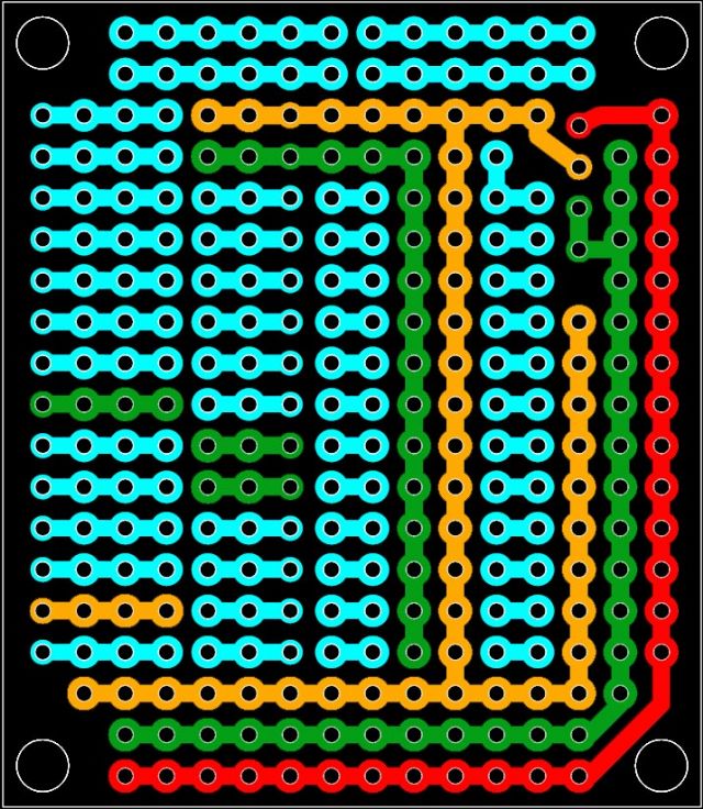
I am worried about too many power rails, What do you think.? Mick Mick's uMite Stuff can be found >>> HERE (Kindly hosted by Dontronics) <<< |
||||
bigmik Guru Joined: 20/06/2011 Location: AustraliaPosts: 2914 |
Hi Phil All, I am thinking to remove the rower rails on the bottom 3 rows and make them groups of 3 pads each (or 2 or 4) Mick Mick's uMite Stuff can be found >>> HERE (Kindly hosted by Dontronics) <<< |
||||
| Phil23 Guru Joined: 27/03/2016 Location: AustraliaPosts: 1664 |
All looking pretty useful. Can't see any problem getting rid of the lower power rails, there's plenty of other places to grab the volts. I think spare pad for connectors is more important. For example, if I built my heat pump controller on it I'd need five resistors for the resistors on the thermistors, 5 two pin Moles connectors to plug them into. 5 or 6 pin connector for the ESP-01 on a lead, and a similar 4 for the HC-12. No display required; but it would probably end up needing a few more connectors for outputs planned. And the intended flow meter; Power of course... So yeah, the power rails could probably be reduced for the sake of more external connection space. Cheers. |
||||
bigmik Guru Joined: 20/06/2011 Location: AustraliaPosts: 2914 |
Phil, All, OK, what about this one? 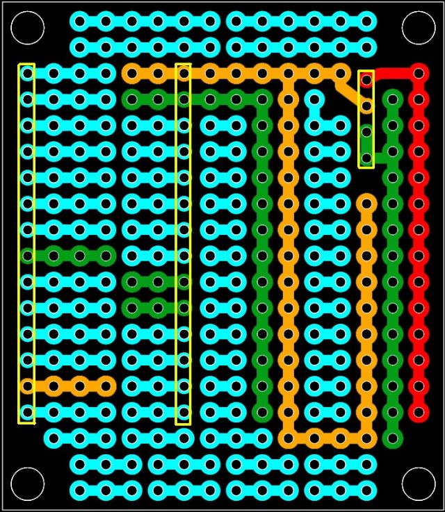
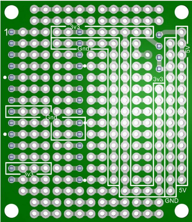
Kind Regards, Mick Mick's uMite Stuff can be found >>> HERE (Kindly hosted by Dontronics) <<< |
||||
| Phil23 Guru Joined: 27/03/2016 Location: AustraliaPosts: 1664 |
looks pretty good. The 4 six hole strips could be broken by the user if they wanted something different. Or partially broken for headers & still maintaining an earth. They would just need to cut a track if required. Phil. |
||||
| Phil23 Guru Joined: 27/03/2016 Location: AustraliaPosts: 1664 |
Given that a couple of my MM's here will be "No Display Required", this will be a great solution for their small component count. All they need is I/O & Wifi plus 433MHz Coms to report to the Master. Both Radio modules will be on short leads to provide some physical device separation. Phil. |
||||
bigmik Guru Joined: 20/06/2011 Location: AustraliaPosts: 2914 |
GDay Phil, All, One last attempt then. I have changed the bottom groups of 3 into groups of 2 going Vertical this gives access to a 12 pin header (or 2 x 6 or 3 x 4 etc) 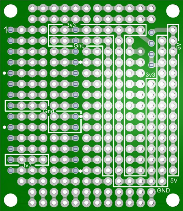
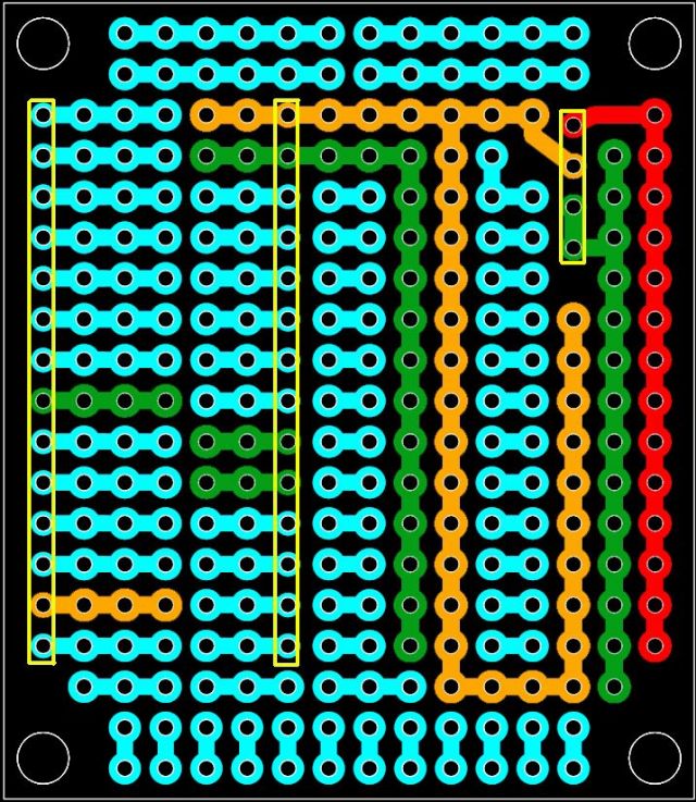
If interested I will post this project and Gerber files and I will get them made next time I order some circuit boards. Kind Regards, Mick Mick's uMite Stuff can be found >>> HERE (Kindly hosted by Dontronics) <<< |
||||
bigmik Guru Joined: 20/06/2011 Location: AustraliaPosts: 2914 |
OK All, I have sent them off to be manufactured, Price `should' be $3each assuming they are happy with the Number of holes (they sometimes baulk at them). I only paid for slow boat from china shipping so I should have them in 3-4 weeks.. PM me if interested and when they arrive I will notify you.. Kind Regards, Mick Mick's uMite Stuff can be found >>> HERE (Kindly hosted by Dontronics) <<< |
||||
bigmik Guru Joined: 20/06/2011 Location: AustraliaPosts: 2914 |
Well, The boards have been shipped, I should have them in about 2 weeks time. They look great, strangely there is a single pad (near the upper left in this picture) that has a solder mask over the top. Not sure why but in the scheme of things is not an issue. 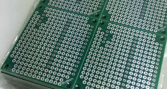
Kind Regards, Mick Mick's uMite Stuff can be found >>> HERE (Kindly hosted by Dontronics) <<< |
||||
| Phil23 Guru Joined: 27/03/2016 Location: AustraliaPosts: 1664 |
Not exactly sure which pad you are referring to Mick. Do you mean the one in 4 & down 5 from the top left? Phil. |
||||
bigmik Guru Joined: 20/06/2011 Location: AustraliaPosts: 2914 |
Yes Phil, That is it.. Not going to cause any grief I am sure.. If you look closely at the 3D impression in the 3rd post on this page you will see it on the top image... 5 down 4 from the RIGHT. As I havent got my boards yet I cannot confirm all others are ok, but I suspect that will be the only pad with this issue. Kind Regards, Mick Mick's uMite Stuff can be found >>> HERE (Kindly hosted by Dontronics) <<< |
||||
bigmik Guru Joined: 20/06/2011 Location: AustraliaPosts: 2914 |
Hi All, The PCBs are here and they look great, Of course these are designed to mate with my MuP, either Ver2 (slightly offset) or Ver3 (perfect alignment). The hole with the GREEN solder mask covering it was caused by me using a VIA instead of a pad and as I selected "tented Vias" meaning cover with green mask, it got painted... Oh Well. These are now available, I havent yet done a manual but I think it is more or less self explanatory. The only `gotcha' is that if you cut any track you need to cut top and bottom as I designed it so we had plated holes for added strength of the pads. I have these available now for $3Aus each plus postage of 1$ in Australia or $3 overseas (max 6 boards for this price due to weight limit). If interested please email me or use PM on the Back Shed. As promised here are the Gerber files if anyone is keen enough to get their own boards made up. 2016-08-25_075338_MuP-Proto.zip Kind Regards, Mick Mick's uMite Stuff can be found >>> HERE (Kindly hosted by Dontronics) <<< |
||||