
|
|
Forum Index : Microcontroller and PC projects : pic32MZ EF 100 pin board sn-7x
| Author | Message | ||||
| robert.rozee Guru Joined: 31/12/2012 Location: New ZealandPosts: 2294 |
a 1455 with ascii ICSP f/w is a bit like an engine crane that costs nothing, and can be built into your ferrari's ignition key. not to mention, if you do ever need to make use of it, it can save a whole lot of hassles and end-user expense. cheers, rob :-) |
||||
| isochronic Guru Joined: 21/01/2012 Location: AustraliaPosts: 689 |
I have confirmed that. |
||||
| robert.rozee Guru Joined: 31/12/2012 Location: New ZealandPosts: 2294 |
you should raise this with peter mather (matherp), as he wrote the 1455 code and is maintaining it. the fix may be simple. cheers, rob :-) |
||||
bigmik Guru Joined: 20/06/2011 Location: AustraliaPosts: 2870 |
Hi Stu, All, I can confirm that the mcp2221 is `basically' the same (uses the same driver as the MicroBlock's U2SP) minus the programming feature of the MicroBlocks U2SP and MatherP's Open source version of the chip. As to setting the serial line LOW is that the USB side? That could be a function of the USB module that is flashed into the '1455. Now MicroBlock's U2SP uses the Microchip USB module and may actually do the same as the mcp2221 chip, the MatherP o/s chip (this really needs a nice name) uses a freeware USB stack (I forget the name off hand) and is most likely the difference you see there. As to extra `baggage' with the programming feature, I have to disagree as it is there for FREE as an option (in both options of the chip) if you chose not to use it so be-it but if you do not have access to a pickit 3 (say I am at work and my PK3 is at home) you can still update the firmware with a simple program (PIC32PROG.EXE) Kind Regards, Mick Mick's uMite Stuff can be found >>> HERE (Kindly hosted by Dontronics) <<< |
||||
| bigmik Guru Joined: 20/06/2011 Location: AustraliaPosts: 2870 |
GDay Stu, All, You mentioned somewhere that your sn-7x supports the pic16f1454/5 sub chip but I can't find a 14 pin footprint anywhere for it. Was I mistaken? I found the tiny XTAL Oscillator pads and think that may be exactly the one I have coming. Boy is it tiny.. Regards, Mick Mick's uMite Stuff can be found >>> HERE (Kindly hosted by Dontronics) <<< |
||||
| isochronic Guru Joined: 21/01/2012 Location: AustraliaPosts: 689 |
The mcp2221a uses the lower 14 pins of the 20 pin footprint - pin 1 is the same for both. So the 1455 *should* be ok doing the same. ed-You can see the 14-pin ic placement on the photo, you have to magnify the screen a bit, I'll rustle up a diagram as well. The serial i/o lines use three resistors as isolation safeguards, two are a voltage divider to drop the 5v from the serial chip to the pic32 3.3v, the other is just a safeguard for the 3.3v from the pic32 to the serial chip. Two of these have different placements connecting to the 14 pin and 20 pinners as the i/o pins are different. BTW here is a more presentable schematic  2017-02-05_130239_sn-7xrevb.zip I think RS and element14 have the oscillators/replacements pretty cheaply, looks like they are pretty generic, bit different to crystals though ! |
||||
| bigmik Guru Joined: 20/06/2011 Location: AustraliaPosts: 2870 |
@Stu, Ahhh, I see much better when I open my eyes.. In my defense it isnt the clearest of pictures. Kind Regards, Mick Mick's uMite Stuff can be found >>> HERE (Kindly hosted by Dontronics) <<< |
||||
| isochronic Guru Joined: 21/01/2012 Location: AustraliaPosts: 689 |
i/o via the 14 pin uart, eg mcp2221a or pic1455 : this shows the component placements in green. Use the two green resistor placements instead of the black. The orange one is the same regardless.  The crystal, etc, are only required for the older mcp2200...time to save some space by chopping that option I think... |
||||
| bigmik Guru Joined: 20/06/2011 Location: AustraliaPosts: 2870 |
Hi Stu, Yes I agree, Now the Oscillator block.. I bought a 3.2mm x 2.5mm Oscillator and as tiny as that is (The size of an SMD 3225 VCap) it was really too big to solder to the sn-7x pads.. You must have chosen an even smaller module than mine.. I would suggest expanding the pads out diagonally so that your small Oscillator and the slightly larger units can be used.. Also some text Legend showing orientation is required. Also the osc is not an easy thing to solder so maybe consider an even larger version. I suggest supporting the PIC16F1454/55 chip and its programming ability for the 100pinner (requires pins 2,3 and 7 to go to the PIC100). I am in the process of photoshopping a changes schem to use the PIC16 in that spot. (Not much really but when I test it all I will publish it here) Anyway it is all meant to be constructive Criticism. Kind Regards, Mick Mick's uMite Stuff can be found >>> HERE (Kindly hosted by Dontronics) <<< |
||||
| isochronic Guru Joined: 21/01/2012 Location: AustraliaPosts: 689 |
Fair and rational comments, no worries ! The oscillator listed in the component list matches the pads well, and solders OK. I agree it is small, and a larger one would assist things. http://au.element14.com/abracon/asdmb-24-000mhz-lc-t/mems-osc-24mhz-2-5-x-2mm-lvcmos/dp/2467879 (ed) The ICSP pins work for reflashing with a pickit3 as usual. For the next iteration, I will drop the 2200 option and bring the three 1455 programming lines to a three-pin header just below it. That will allow people (that do not have a pickit3) to use a little 3-wire jump cable to be used when/if reflashing is required, and prevent incidental reflashing access when it is not intended. |
||||
| isochronic Guru Joined: 21/01/2012 Location: AustraliaPosts: 689 |
BTW these are available at oshpark as a shared project, (gerbers and/or order) https://www.oshpark.com/shared_projects/46O0LmyP or look for sn-7xfinalrevBgerb.zip I also have a doubled panelised version, which gives a "classroom set" ie 20 for the US $10 + postage (pcbway), enquiries welcome (ed - as it happens the double panel fits the educational Eagle license pcb size limit. Most other parts can obtained at Altronics ) |
||||
| isochronic Guru Joined: 21/01/2012 Location: AustraliaPosts: 689 |
I can assure everyone, that although the electrons used by these boards are getting slightly rusty due to apparent constructor memory loss in some cases, every electron remains.. 100 % Microsoft compatible !!!  |
||||
disco4now Guru Joined: 18/12/2014 Location: AustraliaPosts: 844 |
Hi Stuart, I have build a bare bones sn7x with the board you sent. It works so I have progressed to SMD 0603 and 100 pin chips now. Holding them with a small flat screwdriver is the trick, but still hard to get them straight as you can see. 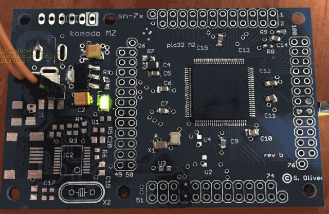  A couple of things that had me scratching my head. 1. The circuit diagram has R1 and LED1 shown in reverse order to how they are connected on the board. i.e 3.3v --> R1 --> LED1 --> GND on the circuit but 3.3v --> LED1 -->R1 --> GND on the board. This showed up when I was trying to work out which way around to put C2 and C3. 2. I assumed I could just connect the console to pins 57/58 as these went to the MCP2221a which I did not install. On power up it would not talk to me. The MMBasic watchdog on pin 99 appeared to be pulsing indicating it was running. The Extreme manual says the console is on 85/86 for the 100 pin MZ chip so I tried the console on 85/86 and it talked OK. Can you confirm whether it would work via the MCP2221a if it was installed or does it need to go to the console pins too? Regards Gerry Latest F4 Latest H7 |
||||
| isochronic Guru Joined: 21/01/2012 Location: AustraliaPosts: 689 |
Good to see ! Thanks for having a go, and the feedback 1) Reverse order of led/resistor - I think you are right on that, my apologies. I will update the schematic so it makes more sense. 2) The usb-console connection runs via usb-direct. To use that, there is a 0 ohm "resistor" link (ie wire) (U4) to supply power to the pic ic usb , and also a 1k resistor (U3) connecting the pic to the usb line. Put those in and you should be able to connect up via the usb-direct (socket on other side of board). The usb-serial bridge on 57/58 was designed to be an auxiliary serial bridge, for other software. However I think the Micromite COM3 serial connections should be able to use it as well (I think there is a basic redirect command to connect via com ports - (??) others would know a lot more here). *(ed)* There is also some flexibility built in. Above the mcp2221a there are two vias that you could solder the pic RX/TX i/o to, and there is a point where the 2221 RX/TX tracks to the 57/58 pins can be cut, er, disconnected easily. So other pins (eg 85/86) could use the 2221a OK as well I think. Let me know if you need more info there. 3) I hope that is 5v in , only.. |
||||
| disco4now Guru Joined: 18/12/2014 Location: AustraliaPosts: 844 |
OK makes sense now.I have not used the usb-direct before so missed the point its where the USB console that MMBasic understands lives and that the MCP2221a is an additional USB-Serial adapter currently connected to pins 57/58 which is COM3 in MMBasic. If you revise the circuit diagram in might be worthwhile to show the MMBasic console pins 85/86 on the chip. Yes only 5v on those connects you see. Regards Gerry Latest F4 Latest H7 |
||||
| isochronic Guru Joined: 21/01/2012 Location: AustraliaPosts: 689 |
That's a good idea, it would make it clearer too. PS Well done for venturing into 0603 stuff, they are really small. [Too small if you ask me.] A powerful hands-free magnifier helped a lot, and eventually to handle them I got some cheap tweezers at a local chemist (!). Pre-soldering one pcb pad and then sliding the component into place works well. |
||||
| Boppa Guru Joined: 08/11/2016 Location: AustraliaPosts: 814 |
I was involved in repairing industrial s.m. stuff for many years I found the lit 25x magnifiers on the adjustable arm a godsend, also I found to prevent muscle tremors being awkward, I had a mousepad with the gel wrist support handy to use, resting your wrist on it while soldering made it much easier Also handy if you are extremely shortsighted like I am (7 and 7.5 on my glasses ie coke bottles lol) I often look over the top and bring the board right up against my face, doing that I an see clearly to within a few centimeters of my eyes Basically builtin closeup magnifiers  |
||||
| zeitfest Guru Joined: 31/07/2019 Location: AustraliaPosts: 396 |
Update : I have put these in the public domain new stub with a label update. |
||||
