
|

|
Forum Index : Microcontroller and PC projects : APNAW - I told you I dad an idea...
| Author | Message | ||||
| Mixtel90 Guru Joined: 05/10/2019 Location: United KingdomPosts: 6772 |
A Pico, Not A Wii Just for fun. No apologies, this is only intended for gaming. :) This isn't a completed design, obviously, but it brings together some ideas I've intended to try. Uses the new 44-pin version of the Pico 2. :) Add 2 extra pins on each side to connect D+, D- and GP25. You can restore it to normal later by taking your link wires to the TPs off and snapping off the extra pins. The WII sockets support the DD pins so detect them going high to see if a controller is plugged in. (I need external pull down resistors, forgot - sorry). Uses a 4-way DIL switch. 1 & 2 isolate D+ and D- while installing MMBasic. 3 overrides the GP21 signal to the LED, making it indicate Power On. 4 pulls GP20 low. It could be used to, for example, instruct an auto-run program to abort while testing it. There must be other uses. :) If switch 3 is off you have full control over the LED. The Red side is fed from GP25 and replaces the heartbeat. The other side is fed from GP21. You can PWM these or whatever. I have some Red/Blue LEDs now which are rather nice. :) The WII connectors are a little close together really, but just about manageable, I think. I can't get them any further apart without having to use a micro SD socket. You don't escape SMD soldering anyway as the HDMI socket is SMD as are its 0805 resistors. Mick Zilog Inside! nascom.info for Nascom & Gemini Preliminary MMBasic docs & my PCB designs |
||||
| javavi Senior Member Joined: 01/10/2023 Location: UkrainePosts: 203 |
You can also try to fit a VGA video output there, connected in parallel to the HDMI with its own resistors. This solution has already been tested in other projects and does not interfere with each other's work. Also implement a VGA color bit depth switch VGA121/222 for the VGA, which will make it possible to port many console emulators to this board. |
||||
| Mixtel90 Guru Joined: 05/10/2019 Location: United KingdomPosts: 6772 |
Not possible in the space available, sorry. I've done designs that could take either connector so you could build them as either HDMI or VGA, but not both. To get both connectors in simply takes up too much rear panel space unless you do it that way. In this particular case I've arranged the positions of the Pico and HDMI connector precisely to get the resistors to take the minimum space and get reasonable track length matching. Trying to put the VGA connector over the HDMI simply doesn't work. Mick Zilog Inside! nascom.info for Nascom & Gemini Preliminary MMBasic docs & my PCB designs |
||||
| javavi Senior Member Joined: 01/10/2023 Location: UkrainePosts: 203 |
Talk about the minimum length of the HDMI tracks on the board is untenable since the cable is much longer, here it may be a matter of their identical length, but it is not so critical. Yes, in the dimensions of your case, perhaps everything will not fit, I would just like to get a universal design that could work with both VGA and HDMI video output. Once again, I inform you that such a solution with parallel connection of two video outputs to Pico2 has already been tested and works fine. There is also a way to automatically detect the type of connected video interface when starting the program based on the state of the input ports. |
||||
| Mixtel90 Guru Joined: 05/10/2019 Location: United KingdomPosts: 6772 |
Do you want a design to test it with? I may be able to do that, but it will be very limited in other respects if the board size is to be kept to a reasonable size. The current design would have to lose the rear USB sockets in order to get the VGA connector in. There is no space to move them to the front unless I force a micro SD card. I don't want to exceed 100mm x 100mm PCB size if possible as the cost from JLCPCB goes up. The individual wiring within the HDMI leads is almost exactly identical. It's not the overall length that's the problem, it's the phase difference between the four channels that matters. The data lines have to stay in phase with the clock and the data is on both the leading and falling edges of that. And it's a fast clock. You don't have a lot of leeway on the PCB really. We are only getting away with it at the moment because we aren't using the full capabilities of HDMI. I suspect your circuit may need some careful layout to prevent the VGA traces from interfering with the HDMI. At the very least they will introduce additional capacitance to GND, degrading the data edges. That doesn't mean that it's not possible, but it may mean that it doesn't work on a first attempt. :) It may even work fine with the wiring hanging in mid-air but not when you put it on a PCB. VGA RGB222 isn't currently possible in MMBasic, by the way. Only RGB121 is supported. . Edited 2024-11-05 00:06 by Mixtel90 Mick Zilog Inside! nascom.info for Nascom & Gemini Preliminary MMBasic docs & my PCB designs |
||||
| javavi Senior Member Joined: 01/10/2023 Location: UkrainePosts: 203 |
Do you have to use a ready-made case for this device? With a ready-made case, you are limited to its two sides and the internal screws for fastening the board. It is possible to develop a case model for printing plastic on a 3D printer, or for cutting acrylic on a laser. This is how it might look, normal for an amateur design. 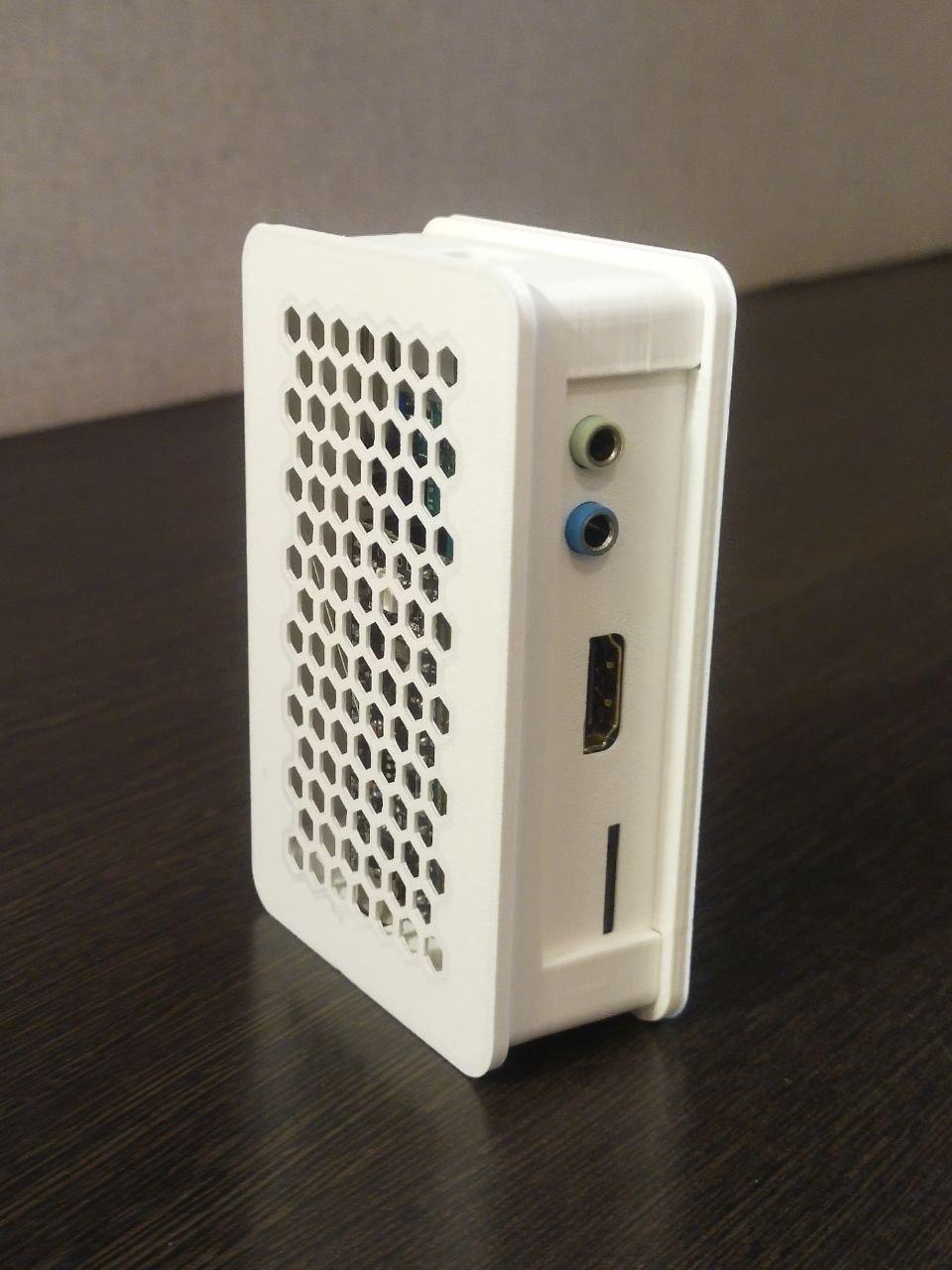 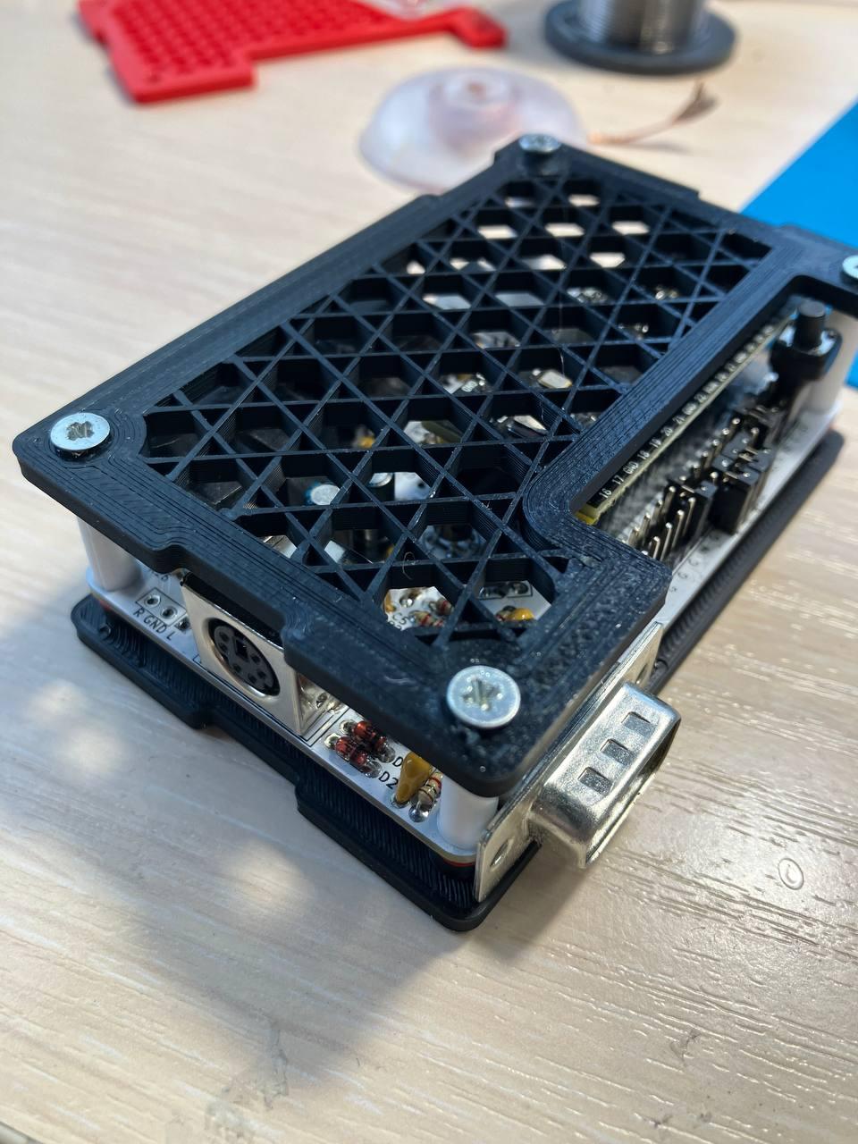 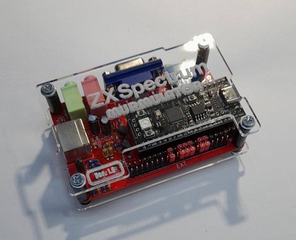 Edited 2024-11-05 00:40 by javavi |
||||
| javavi Senior Member Joined: 01/10/2023 Location: UkrainePosts: 203 |
Yes, I understand that. I was saying that if this device has a switchable VGA222/121 circuit, then in addition to PicoMite (VGA121), it will be easy to port many existing emulator projects to it (Spectrum, Atari800, NES, GameBoy, etc.) that work on the VGA222 circuit. |
||||
| Volhout Guru Joined: 05/03/2018 Location: NetherlandsPosts: 4222 |
Hi MIck, I could have known. This morning you made a remark "I have an idea", and now it is done. ... Great. I was under the impression that you where doing a small DE9 -> dual WII adapter for the other design (the SPGA). @javavi: I know the murmulator (actually I think there are more than one design. This one looks different from my memory). It is extremely compact. But... This is just my taste.. I like designs that have all IO in front and back. And for me there is no requirement for "small". A shoe-box size (lower profile) is okay as well. I am not stocking so many that I need a big shelf. One or 2 is enough. Although.... with current changes I have to decide on a platform to continue with. There are so many options (VGA/HDMI, PS2/USB, WII/USB controller, PWM audio/DAC/VS1053, SD/uSD, 2040/2350).. I'll hang in on this forum a bit, to see where the sea brings us. Maybe I am just old fashioned... Volhout Edited 2024-11-05 00:57 by Volhout PicomiteVGA PETSCII ROBOTS |
||||
| Mixtel90 Guru Joined: 05/10/2019 Location: United KingdomPosts: 6772 |
It looks like you already have a design. :) Have you seen a system with two sockets that works or has it just been a design that has been done? No idea how that YD-RP2040 could generate DVI/HDMI though. It won't overclock to that speed. Mine die at just over 250MHz. They only just make it to VGA. lol I never use custom cases. I can't make them and it's not economic to get them made in one-off quantities. They are really nice, but just not practical for me personally. An idea... How about 3D printed "feet" to add onto a Hammond case to stand it on end? That might be interesting. . Edited 2024-11-05 01:00 by Mixtel90 Mick Zilog Inside! nascom.info for Nascom & Gemini Preliminary MMBasic docs & my PCB designs |
||||
| Sasquatch Guru Joined: 08/05/2020 Location: United StatesPosts: 362 |
I think the issue here is not the trace length but the impedance matching to the cable and the terminating resistors on the other end (and yes, keeping the length of the individual traces matched) Keeping the unmatched trace length short should help the integrity of the high speed differential signals. Note that it is possible to create PCB traces with the proper impedance, but it requires proper trace width, spacing, ground plane, board thickness etc. This is an interesting idea, my question would be, tested at what resolution? We have already seen that HDMI at lower resolutions (i.e. lower frequency HDMI signals) is much more forgiving. It wasn't until Peter implemented the higher horizontal resolutions that I started seeing issues with the HDMI signals on my test setups. Edited 2024-11-05 01:34 by Sasquatch -Carl |
||||
| javavi Senior Member Joined: 01/10/2023 Location: UkrainePosts: 203 |
Here are some examples, there are others. True, HDMI here only works with a resolution of 640x480, but with sound. In parallel to the HDMI, VGA and even a composite video output are connected. 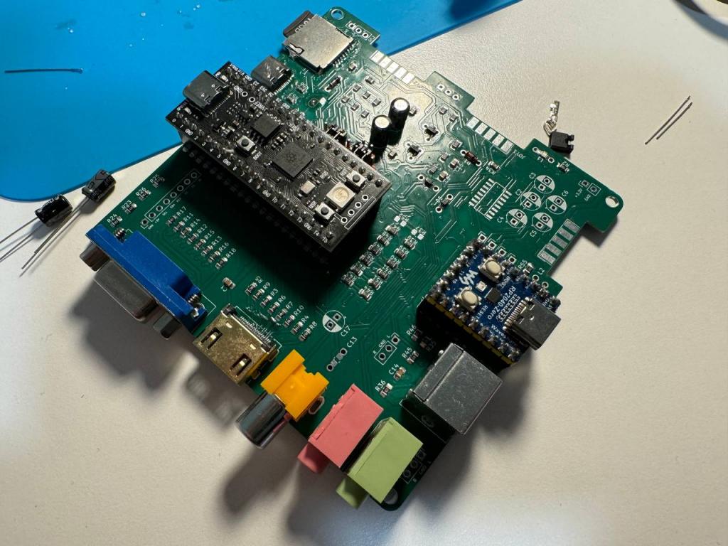 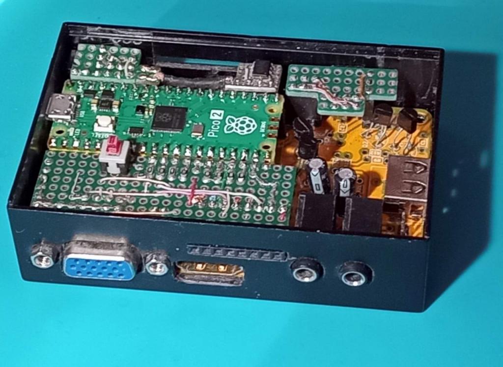 Edited 2024-11-05 01:43 by javavi |
||||
| Mixtel90 Guru Joined: 05/10/2019 Location: United KingdomPosts: 6772 |
The 220R or 270R resistors in the HDMI signal paths at the Pico end don't help the impedance matching in particular. In fact they make it worse. They are current limiters to protect the output drivers in the Pico The terminating impedance is 50R per line, 100R across each pair. This would take about four times the current that the Pico could source while supplying a usable voltage. In order to supply some voltage into the line it's necessary to limit the current and hope that we can get away with the impedance matching! This doesn't affect the phase of the signals reaching the monitor, although it makes a mess of the wave shape. We still have to supply the data signals in phase with the clock so we can't introduce delay lines made from capacitors to GND and very unmatched trace lengths. We can get so far, as I've proved with Alpha, but just how far out we can get I don't know. This is why I've never attempted to fit both VGA and HDMI to the same board. Mick Zilog Inside! nascom.info for Nascom & Gemini Preliminary MMBasic docs & my PCB designs |
||||
| javavi Senior Member Joined: 01/10/2023 Location: UkrainePosts: 203 |
|
||||
| Sasquatch Guru Joined: 08/05/2020 Location: United StatesPosts: 362 |
I like the idea! I am skeptical that it will work at the higher horizontal resolutions. I think I have all the parts here to at least do some initial testing. If it can work at high resolution on my test rig, a PCB should not be a problem? Then someone will need to try a PCB layout with the understanding that it might not be fully compatible with the Pico2 HDMI firmware. -Carl |
||||
| Mixtel90 Guru Joined: 05/10/2019 Location: United KingdomPosts: 6772 |
I'm mot sure about this on the Pico 2 at the moment. The HSTX port runs *far* faster than a Zero can manage. You will almost certainly be limited to 640x480 in HDMI and that's if you are lucky. The loading on the Pico's pins is also very heavy with those resistor networks and that too will make things marginal. It'll probably work fine in VGA, of course, as it's much less demanding. I love the design though. :) Mick Zilog Inside! nascom.info for Nascom & Gemini Preliminary MMBasic docs & my PCB designs |
||||
| Volhout Guru Joined: 05/03/2018 Location: NetherlandsPosts: 4222 |
They also use pins from the bottom of the pico zero. You could just as well take a normal pico. If you have the 220 ohm resistors close to the PIO pins, vga and hdmi will not be affected much. But you can never plug both. The I2C bus (gp14-15) does not have pull-ups. I wonder if the build in pull-ups will work with a nunchuck. Volhout Edited 2024-11-05 02:34 by Volhout PicomiteVGA PETSCII ROBOTS |
||||
| Mixtel90 Guru Joined: 05/10/2019 Location: United KingdomPosts: 6772 |
The Nunchuck has 1K8 pullups. That's supposedly the best end of the cable to have them from what I've read. :) I think I've managed to get the 2 sockets & switching on a board with a "44-pin" Pico 2. Aiming for the Hammond 1593 case (the square one) because I have a couple. :) They would look nice on end if some feet can be sorted out. They are slightly deeper than the cheap case, which makes things easier. Edited 2024-11-05 02:50 by Mixtel90 Mick Zilog Inside! nascom.info for Nascom & Gemini Preliminary MMBasic docs & my PCB designs |
||||