|

|
Forum Index : Microcontroller and PC projects : One for the amplifier experts
| Page 1 of 3 |
|||||
| Author | Message | ||||
| PhenixRising Guru Joined: 07/11/2023 Location: United KingdomPosts: 857 |
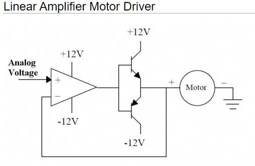
I have been searching for a full schematic for something like this:  It's for my small brush-type motors. My command signal is +- 10V where 10V drives max current in one direction and -10V drives max current in the other direction and of course, 0V is null. Current output <2A but adjustable gain (pot?) would be a plus. I had several of these, back in the 80's but now I can't seem to locate one and I'm useless at designing this stuff  |
||||
| Volhout Guru Joined: 05/03/2018 Location: NetherlandsPosts: 4222 |
Hi Phenix, The circuit you provided has voltage feedback, not current feedback. I basically makes sure the voltage from the DAC is put across the motor terminals. So the motor received -10V...+10V, regardless the current that is running. Why not look at DC motor control IC's ? These provide all the control you need, and sometime even have a build in power stage for < 2A. Such as the BD62130 (Rohm) or A4952(Allegro). You control these directly from 2 PWM outputs on the pico. Volhout EDIT: if you insist in going linear, I would look at car radio amplifier IC's. These provide the current, and the protection, at low cost. Then combine these with a simple opamp that does the +/- 10V conversion to the car amplifer IC input and feedback (the car amplifier IC's do not have the DC accuracy you may require). Edited 2024-09-10 20:55 by Volhout PicomiteVGA PETSCII ROBOTS |
||||
| PhenixRising Guru Joined: 07/11/2023 Location: United KingdomPosts: 857 |
Oh, the intention of the schematic was to merely illustrate that I am looking for something that will accept an analogue command...don't want PWM, I have lots of those. |
||||
| Volhout Guru Joined: 05/03/2018 Location: NetherlandsPosts: 4222 |
Hi Phenix, Cheap audio power output stages suitable for 12V motors 2A are: TDA7377 or 7379. These require a single supply (configure to dual full bridge configuration), can drive 2 motors. Need input circuit to adapt to +/-10V since they have a single supply. TDA7264. Dual supply (basically 2 power opamps in one housing), can drive 2 motors. Need only voltage divider to connect to +/-10V. Breadboard friendly. Regards, Volhout P.S. I only suggest these (versus simply building one from OPAMP and power transistors) because these have build in thermal protection and such. So they are more robust than anything you can throw together without giving it a thorough design cycle. Edited 2024-09-10 21:20 by Volhout PicomiteVGA PETSCII ROBOTS |
||||
| PhenixRising Guru Joined: 07/11/2023 Location: United KingdomPosts: 857 |
Much appreciated, Harm  It's only for my desktop simulator but I can't use the PicoMite's PWM as it takes a full millisecond which is a killer. Can we possibly do better with a PIO PWM?  |
||||
| Volhout Guru Joined: 05/03/2018 Location: NetherlandsPosts: 4222 |
And they are cheap... TDA7264 Volhout PicomiteVGA PETSCII ROBOTS |
||||
| PhenixRising Guru Joined: 07/11/2023 Location: United KingdomPosts: 857 |
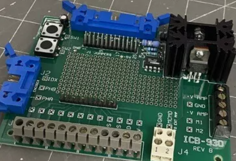
How about this? |
||||
| Volhout Guru Joined: 05/03/2018 Location: NetherlandsPosts: 4222 |
Why not, that is a single channel, but should be usable. You can also find them at Aliexpress for like 7 euro a pair (2 pieces). Volhout PicomiteVGA PETSCII ROBOTS |
||||
| stanleyella Guru Joined: 25/06/2022 Location: United KingdomPosts: 2120 |
you can modify a servo for continuous rotation. old vid https://www.youtube.com/watch?v=aa9sXwqO8GY uses pulse out as normal for servos but can be better than h-bridge Edited 2024-09-11 03:02 by stanleyella |
||||
| PhenixRising Guru Joined: 07/11/2023 Location: United KingdomPosts: 857 |
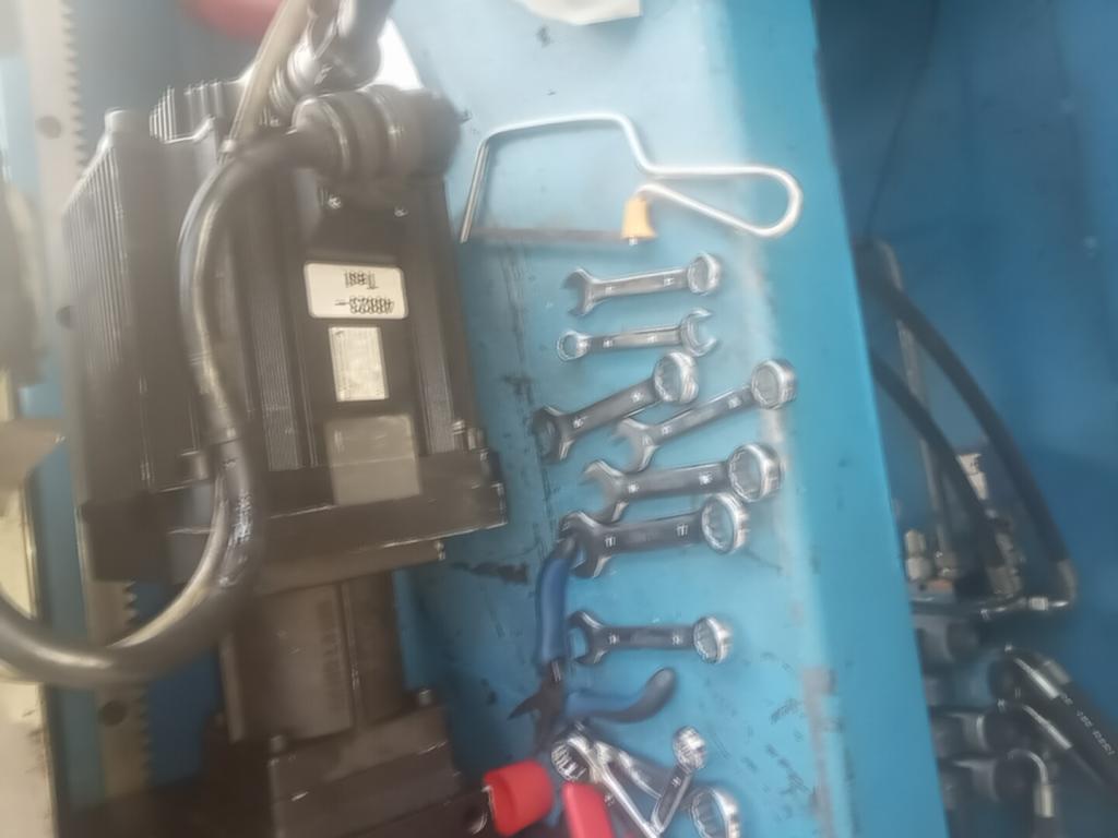
 Oh it's continuous rotation alright...Just hoping it doesn't "continue" beyond where the PicoMite tells it to go.  4.5KW and €9,000 if I wreck it. In my world, a servo motor is something that powers a machine tool However, I use miniature versions on the desktop to develop capabilities such as linear, circular, helical interpolation, electronic gearing etc. |
||||
| stanleyella Guru Joined: 25/06/2022 Location: United KingdomPosts: 2120 |
is the magnetic field so strong spanners stick? :) |
||||
| PhenixRising Guru Joined: 07/11/2023 Location: United KingdomPosts: 857 |
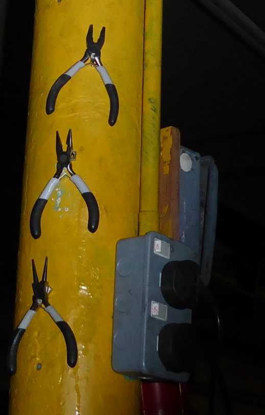
My tools are weird like that   |
||||
Quazee137 Guru Joined: 07/08/2016 Location: United StatesPosts: 567 |
here is a few items to look at audio amp motor driver SunBEAM Seeker Bot Lobsterbot Have FUN Quazee137 |
||||
| PeterB Guru Joined: 05/02/2015 Location: AustraliaPosts: 651 |
G'day All Are we trying to control speed or position ? Peter |
||||
| PhenixRising Guru Joined: 07/11/2023 Location: United KingdomPosts: 857 |
The PicoMite handles all aspects of motion; velocity, accel, decel, and position via an incremental encoder. Industrial servo controllers accept an analogue motor command, ranging from -10V to +10V and this is provided by the PicoMite via a 12bit DAC. I want to transconduct this signal to provide current to a brush-type motor that I have as a desktop development rig. The one that I had in the 80's was a very simple affair. I have no-end of H-bridge drivers but these are driven via PWM which I don't want. |
||||
| Mixtel90 Guru Joined: 05/10/2019 Location: United KingdomPosts: 6778 |
Using a couple of op amps powered from +/- supplies (probably +/- 15V depending on the op amp capabilities) you can first shift the zero of the DAC or PWM signal to get a signal that swings around the zero point rather than mid supply. Then you can amplify that to get +/10V. Is that the sort of thing you are looking for? Mick Zilog Inside! nascom.info for Nascom & Gemini Preliminary MMBasic docs & my PCB designs |
||||
| PhenixRising Guru Joined: 07/11/2023 Location: United KingdomPosts: 857 |
I actually located an image:  The amp requires a +/- PSU (IIRC, 24Vmax) The motor command +/- 10V is merely a reference; 10V command = max motor-current say, clockwise and -10V command = max motor-current counter-clockwise. There was a gain-setting resistor to scale the amps/volt of motor-command. |
||||
| Mixtel90 Guru Joined: 05/10/2019 Location: United KingdomPosts: 6778 |
input---------! + \ 0-3V3 ! \ ! -+-------! + \ ! / ! ! \ +-! - / ! ! --+------ -10 to +10 ! ! ! / ! 3V3 -[4K4]=-+--[4K7]-- + +-! - / - ! 15K ! - ! ! +----------+ ! - 5K - ! 0V Adjusting the 5K sets the gain adjusting the 4K4 changes the centre point Be careful with op amps for this. To get this output you need over 20V supply as few op amps will swing to the supply rails. Mick Zilog Inside! nascom.info for Nascom & Gemini Preliminary MMBasic docs & my PCB designs |
||||
| PhenixRising Guru Joined: 07/11/2023 Location: United KingdomPosts: 857 |
Thanks Mick....I can use that  ...BUT that's similar to what I have. The -/+ 10V is the input to the motor-driver (amplifier). ...BUT that's similar to what I have. The -/+ 10V is the input to the motor-driver (amplifier).The amplifier can output any amount of current, depending on what it is. If my actual machine-driver has a current-gain setting of 3A/Volt then +10v will give me 30A. On my desktop, I might have +/-24V and I would need to set the linear-amp gain to suit the motor's max current (not sure what it can handle). |
||||
| Mixtel90 Guru Joined: 05/10/2019 Location: United KingdomPosts: 6778 |
So it's the actual amplifier that you are looking for? The sketch right at the beginning is something to work with. Personally I'd use a full H bridge as torque is proportional to the square of the armature current and a full H gives you twice the voltage therefore 4 times the torque. The second half-H is driven by an inverter from the input to the driven half-H. I'd look at the possibility of fitting some current feedback somehow too. It would be sad to see smoke arising from the bridge devices if the load gets a bit sticky. One of the "ring" type hall effect sensors would be good here as they can be bi-directional and actually fitted to the motor output, although you could equally well use one unidirectionally on the main supply to the H bridge. Any linear output devices will get *HOT* if you are considering 30A. It might be an idea to consider some sort of PWM and let the load's inertia act as the filter. That way your output devices are always hard on or hard off - juicy MOSFET territory, but P-channel might be difficult to get so it gets more complex. Mick Zilog Inside! nascom.info for Nascom & Gemini Preliminary MMBasic docs & my PCB designs |
||||
| Page 1 of 3 |
|||||