|

|
Forum Index : Microcontroller and PC projects : Hardware bug in RP2350
| Page 1 of 3 |
|||||
| Author | Message | ||||
| cosmic frog Senior Member Joined: 09/02/2012 Location: United KingdomPosts: 284 |
"A Surprise Hardware Bug in Raspberry Pi's RP2350 Leads to Unexpected Pull-Down Behavior" Link Dave. |
||||
| Volhout Guru Joined: 05/03/2018 Location: NetherlandsPosts: 4222 |
That is a more serious bug than the RP2040's ADC accuracy. And why only on bank 0. Vohout Edited 2024-08-28 05:46 by Volhout PicomiteVGA PETSCII ROBOTS |
||||
| EDNEDN Senior Member Joined: 18/02/2023 Location: United StatesPosts: 118 |
I hope they rev the chip quickly to get rid of this. If they do, there won't be that many bad chips out in the wild. I think I'll wait 6 months to get anything with a RP2350 in it. |
||||
| Volhout Guru Joined: 05/03/2018 Location: NetherlandsPosts: 4222 |
Actually, this bug will most likely not be solved ever. Applying an external pull-down resistor, and never using the internal pull-down, is a good solution. If you know what new maskings of a chip costs, you would not expect a change. The ADC bug in the RP2040 is also never solved (after 3 years in the field). I suggest Peter will remove the "pull_down" option on the SETPIN command to avoid problems. Volhout Edited 2024-08-28 06:57 by Volhout PicomiteVGA PETSCII ROBOTS |
||||
| Mixtel90 Guru Joined: 05/10/2019 Location: United KingdomPosts: 6778 |
It could even be twiddled so that it appears to be right in MMBasic by adding extra commands when an instruction is given to control a pin while pull downs are active. It's almost certainly possible but probably not really worth the effort once you know about the bug. Mick Zilog Inside! nascom.info for Nascom & Gemini Preliminary MMBasic docs & my PCB designs |
||||
| EDNEDN Senior Member Joined: 18/02/2023 Location: United StatesPosts: 118 |
It just seems very sloppy to ask a vendor or partner to make a minor tweak to the output cell and then not even review the change. Especially when the change is a totally different circuit and doesn't even resemble the original GPIO cell. "I suggest Peter will remove the "pull_down" option on the SETPIN command to avoid problems." Yup... Fix it in the software... Edited 2024-08-28 07:50 by EDNEDN |
||||
TassyJim Guru Joined: 07/08/2011 Location: AustraliaPosts: 6097 |
Using external pull-downs is an easy solution for standard inputs but how many devices with special comms protocols use pulldowns in the firmware? That can make life interesting. My modules are waiting at the post office so I can see a lot of testing coming up. I hope most use pull-ups, not pull-downs. Jim VK7JH MMedit MMBasic Help |
||||
| Volhout Guru Joined: 05/03/2018 Location: NetherlandsPosts: 4222 |
All, In my testing today I have seen a Pico2 GPIO pin stuck at 2V (with a scope with 10meg probe impedance). This is on a Pico2. The pin was set to input (no pull-down enabled). The pin returned to low or high state when actively driven, But in normal INPUT state it stayed at 1.95V before driven hard. I have checked on the internet, and there is 1 other guy making the same observation. without pull-down This means that if you have a GPIO pin on a 2350 that is not driven with a low impedance, it potentially changes level. I have not yet seen it on a ADC enabled pin. That would be a real drama, since ADC's are typically not hard driven. Volhout EDIT: looking at the noise in the forums on this bug, RP might be forced to do new mask for the chip, or accept it will not be the success the 2040 was. Edited 2024-08-28 22:28 by Volhout PicomiteVGA PETSCII ROBOTS |
||||
| Volhout Guru Joined: 05/03/2018 Location: NetherlandsPosts: 4222 |
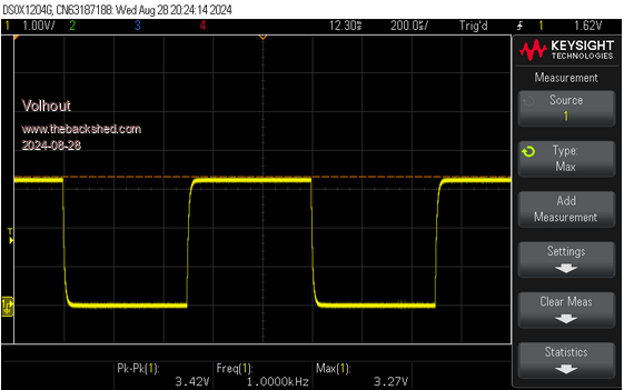
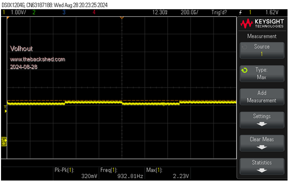
About the bug: It is even more serous than I thought. Look at below pictures. I have a 1kHz signal from a generator (3.3V), looking like this:  With a series resistor of 100k (yes, that is high impedance, but not terribly high) I apply this signal to a Pico2 GPIO pin (in this case GP0). This Pico2 is flashed with MMBasic, but NO PROGRAM IS RUNNING. This is just the default GPIO pin configuration after power up. This is what the signal looks like:  You really need to drive the pin low impedance. High impedance will not work. Forums say that 9k ohm is maximum. Volhout PicomiteVGA PETSCII ROBOTS |
||||
| Mixtel90 Guru Joined: 05/10/2019 Location: United KingdomPosts: 6778 |
Oh dear, that's very poor performance. IIRC the ADC inputs on some PIC ICs had to be driven from 19K or less impedance but that's the lowest I've ever seen - and it didn't apply to digital inputs. This could be a serious problem if it's not restricted to just pull down resistors. Mick Zilog Inside! nascom.info for Nascom & Gemini Preliminary MMBasic docs & my PCB designs |
||||
| PhenixRising Guru Joined: 07/11/2023 Location: United KingdomPosts: 857 |
Hey Harm, So I took your advice re: voltage divider for 5v input. Effectively, this is a 10K pull-down and a 4K7 from the 5V signal. Bit concerned about this because this is the encoder signals. Am I in good shape, do you think? This is only on proto-board so I can re-assign to other pins. Do I understand correctly that this issue only relates to pins 0-7? Or should I switch back to the RP2040? |
||||
| Volhout Guru Joined: 05/03/2018 Location: NetherlandsPosts: 4222 |
Hi Phenix, Effectively your impedance is 10k parallel to 4.7k, something like 3.3k. That should be fine. But this is all relatively new information. I personally fear we did not arrive at the bottom of this pit yet (we have not seen the worst). If you are able to work with the RP2040, I would continue to do that. Comming weeks may reveal more information, and there may be an official press release from RP about what is a safe value to use, and what is not. They may have a better overall view of tolerances, and what we can expect. The 9k ohm is comming from a forum member, in analyzing his particular RP2350. I personally will not design anything right now around the RP2350. Appart from HDMI, it does not bring revolutionary new features (I did not need a 3'rd PIO yet). Maybe ony RAM. But I am not writing any huge programs (like PETSCII) at the moment. I can wait until the dust settles. Volhout Edited 2024-08-28 23:09 by Volhout PicomiteVGA PETSCII ROBOTS |
||||
| Mixtel90 Guru Joined: 05/10/2019 Location: United KingdomPosts: 6778 |
I'd reduce the 10K to 6K8 and reduce the 4k7 to 3k9. It depends on what's driving it though. . Edited 2024-08-28 23:12 by Mixtel90 Mick Zilog Inside! nascom.info for Nascom & Gemini Preliminary MMBasic docs & my PCB designs |
||||
| Volhout Guru Joined: 05/03/2018 Location: NetherlandsPosts: 4222 |
Phenix, If you look at the datasheet, virtually ALL GPIO pins are in bank 0. Not just GP0...GP7. Regards, Volhout EDIT: on my RP2350 Pico2, 10k ohm series impedance works when the signal is perfect (0V/3.3V), 20k ohm definitely not. So on my Pico2, I need 10k or lower as pulldowns. Edited 2024-08-28 23:38 by Volhout PicomiteVGA PETSCII ROBOTS |
||||
| EDNEDN Senior Member Joined: 18/02/2023 Location: United StatesPosts: 118 |
I'm not doing any boards. But I'm in the same camp. I don't want to get a bunch of RP2350's that don't have the proper circuitry to use the GPIO pins however I need. I do like the support for the PSRAM but I have no immediate use for that right now. I can wait. And the more people that feel that way the more likely this gets fixed quickly. |
||||
| Sasquatch Guru Joined: 08/05/2020 Location: United StatesPosts: 362 |
Yes, I can see your point! However, somebody needs to do the testing to find the errors and limitations of the new device. If they do a second revision, we want ALL the known problems fixed. -Carl |
||||
| Volhout Guru Joined: 05/03/2018 Location: NetherlandsPosts: 4222 |
Carl, The doomsday scenario is that RP spin the chip to fix this, and that the surplus of faulty chips end up on cheap chineese clones. So in the years ot come, you will find the faulty chips... not from RP, but potentially on every cheap clone. The faulty chips already exist, potentially millions of them. So what now..? I honestly think that the chip (under this RP2350 name) is already doomed. Volhout Edited 2024-08-29 00:29 by Volhout PicomiteVGA PETSCII ROBOTS |
||||
| Mixtel90 Guru Joined: 05/10/2019 Location: United KingdomPosts: 6778 |
I predict excellent future sales in 10K pull up resistor packages and a loss of pull down input circuits. :) I doubt if RP will fix this. They are more likely to bring forward the next new device (if at all possible) and let this slide quietly into obscurity as it gets overshadowed. There will probably also be a huge claim for damages against that outside supplier. Mick Zilog Inside! nascom.info for Nascom & Gemini Preliminary MMBasic docs & my PCB designs |
||||
| EDNEDN Senior Member Joined: 18/02/2023 Location: United StatesPosts: 118 |
So in the years to come, you will find the faulty chips... not from RP, but potentially on every cheap clone. The faulty chips already exist, potentially millions of them. So what now..? I honestly think that the chip (under this RP2350 name) is already doomed. Yikes!!! That would be horrible. Hopefully if they spin the chip they add an '-A' suffix so this doesn't happen. If the chip becomes something like RP2350-A the end users can do a first level check they have a fixed chip. Of course, with cheap labor the cheap clones will start stenciling a '-A' onto the bad chips and run the plant at full speed. Edited 2024-08-29 00:59 by EDNEDN |
||||
| stanleyella Guru Joined: 25/06/2022 Location: United KingdomPosts: 2120 |
2 pico2 just arrived from pimoroni, was about to solder header pins but just read this thread, downer.. but I only used inbuilt pullups for switching gpio to ground so maybe it won't be a problem , dunno though. sigh |
||||
| Page 1 of 3 |
|||||