|

|
Forum Index : Microcontroller and PC projects : DVI board possibilities
| Author | Message | ||||
| Mixtel90 Guru Joined: 05/10/2019 Location: United KingdomPosts: 6780 |
This is a board that's grown from the VGA versions in my "I got bored" thread. It's not at a stage where it could be built yet, but it gives you an idea. The case is the little Multicomp box that Peter has used, but if it has the MC prefix omitted from it's part number and says Hammond on it it's cheaper. :) The little daughter board at the bottom left carries an LED that's used to illuminate a "secret until lit" logo on the front panel. There are different daughter boards depending on the LED. Mick Zilog Inside! nascom.info for Nascom & Gemini Preliminary MMBasic docs & my PCB designs |
||||
| Volhout Guru Joined: 05/03/2018 Location: NetherlandsPosts: 4223 |
I assume audio is also on HDMI ? If it is not, consider a SPIF chip with build in hardware volume control. I am sure there are libraries for that. There is one RC2040 board with 256 color VGA that uses such audio DAC. Volhout PicomiteVGA PETSCII ROBOTS |
||||
| Mixtel90 Guru Joined: 05/10/2019 Location: United KingdomPosts: 6780 |
No, no audio on DVI. Never heard of those chips either. :) I don't know if the RP2350 could do anything with it. Isn't the audio encoded into the hdmi signal? The HSTX handles all that side, I think. I'm unsure about it anyway. The speakers in TVs and monitors are usually pretty grim, certainly not up to the standard of even mediocre headphones. I've included a pretty good headphone amp and a manual volume control, complete with isolating caps to keep DC off the inputs. That output could be used to drive an amp, amplified speakers or even sensitive passive speakers. . Edited 2024-08-19 06:40 by Mixtel90 Mick Zilog Inside! nascom.info for Nascom & Gemini Preliminary MMBasic docs & my PCB designs |
||||
| lew247 Guru Joined: 23/12/2015 Location: United KingdomPosts: 1702 |
HDMI audio is digital and can be generated by the RP2350 Have you seen Bitbanged DVI on the RP2040 Microcontroller with HDMI and audio support Specifically Using https://github.com/shuichitakano/pico_lib C++ implementation of the HDMI with audio support For picoDVI I do not know if anyone can "translate" the C+ to basic but it shows it's possible to get hdmi compliant audio from the chip |
||||
| Mixtel90 Guru Joined: 05/10/2019 Location: United KingdomPosts: 6780 |
It might be, but at the moment there's no way I can include any hardware if it's needed. So much depends on the work that Peter is doing and what, if anything, he chooses to release. I certainly won't be working in C or C++ under any circumstances. :) When I'm still at the stage of wondering if I can solder an HDMI connector there are so many other things to bother about other than squirting lo-fi audio through it. :) In fact, I'm just playing with a smaller, cheaper board for a Pico 2 + HDMI that can accept a daughter PCB to convert it to Pico + VGA. This one keeps within two 100x100 boards (one for the VGA adapter) as I need something cheap to experiment on. I've had to sacrifice the WII connector, large RTC and the sea of holes but I can have 4x USB now so that's ok. Mick Zilog Inside! nascom.info for Nascom & Gemini Preliminary MMBasic docs & my PCB designs |
||||
| lew247 Guru Joined: 23/12/2015 Location: United KingdomPosts: 1702 |
Only software but unfortunately it's C+ |
||||
| JohnS Guru Joined: 18/11/2011 Location: United KingdomPosts: 3800 |
Love it! C? Or C++? (Or hedging your bets?) John |
||||
| Mixtel90 Guru Joined: 05/10/2019 Location: United KingdomPosts: 6780 |
I've just ordered some test PCBs for the Pico 2, using SMD HDMI connectors. These are 100mm x 100mm and fit the little case, as described earlier. Obviously these are completely untested and at the moment the BOM and schematic are only in my head so it's not a beginners project. Bits are generally from AE. Alpha gerbers.zip The ADC pins aren't used but I've not brought them out to anywhere. The LED is a 5mm version of the WS2812B. The connectors above the top right end of the Pico are for fitting a VGA board that replaces the HDMI if I can't manage to solder it! I have the VGA board design ready just in case. There is a no-copper area at the top right. It's a test area. I'm using 1.2mm white PCB and testing for light transmission. There is a HDMI socket soldering test area on the back of the board near the USB sockets. The pot is an Alpha type, bought from Rapid Electronics. Similar ones without the metal bracket can be found on AE. The socket at the bottom right is a RJ12 6P6C type that I got on ebay IIRC. There are a lot of manufacturers, but these have the notch at the bottom. The two unmarked resistors under the level shifter (which only has 4 pins on each side) are pull-down for the USB and may not be needed. . Edited 2024-08-20 04:31 by Mixtel90 Mick Zilog Inside! nascom.info for Nascom & Gemini Preliminary MMBasic docs & my PCB designs |
||||
| lew247 Guru Joined: 23/12/2015 Location: United KingdomPosts: 1702 |
C++ C++ implementation of the HDMI with audio support For picoDVI |
||||
vegipete Guru Joined: 29/01/2013 Location: CanadaPosts: 1109 |
Here's a whacky idea for an hdmi connector: PCB HDMI connector Pico pins might need remapping - I haven't checked anything. Visit Vegipete's *Mite Library for cool programs. |
||||
| Mixtel90 Guru Joined: 05/10/2019 Location: United KingdomPosts: 6780 |
If he's kept the same relationship to the Pico pins that the "sock" uses (and it looks like he might have) then that should work fine AFAIK. It's the same pin mapping that I'm using so we'll see if it works in a couple of weeks. :) Check with what was said about the special work used for the edge connectors. That's not available in SL6. Personally I'd much prefer the mating surfaces to be gold plated too, but that puts the cost up. Probably a lot cheaper to buy a "sock" or do something with proper connectors. Mick Zilog Inside! nascom.info for Nascom & Gemini Preliminary MMBasic docs & my PCB designs |
||||
| Mixtel90 Guru Joined: 05/10/2019 Location: United KingdomPosts: 6780 |
I've ordered the VGA adapter boards too. I've made these so that you can use one stand-alone as a VGA breakout board. Might be useful for someone. VGAadap gerber.zip If you use SMD resistors and saw the corner of the main board out this could be mounted flat down to replace the HDMI stuff. If it's mounted on pillars over the HDMI then you can split the two green signals to use HDMI or combine them to use VGA. :) The PicoGame logo should work as a secret-until-lit picture. I've ordered 1.2mm white to see if/how well it works. . Edited 2024-08-21 00:19 by Mixtel90 Mick Zilog Inside! nascom.info for Nascom & Gemini Preliminary MMBasic docs & my PCB designs |
||||
| lew247 Guru Joined: 23/12/2015 Location: United KingdomPosts: 1702 |
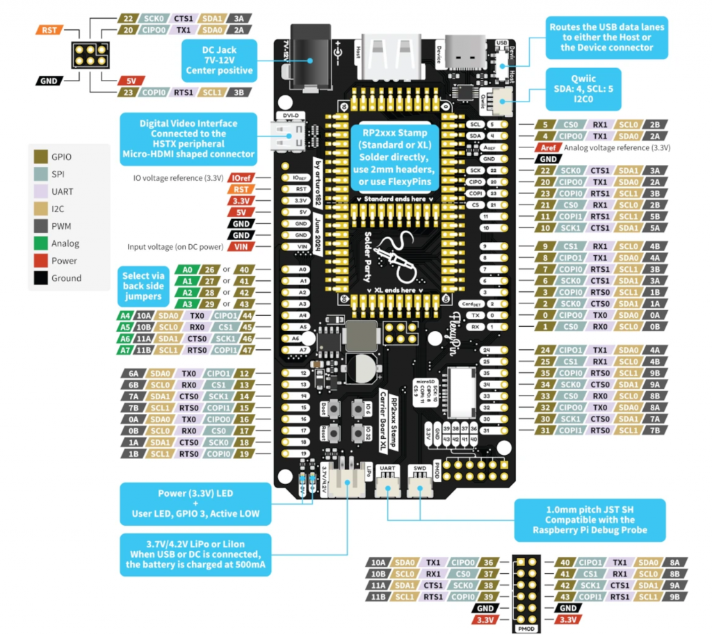
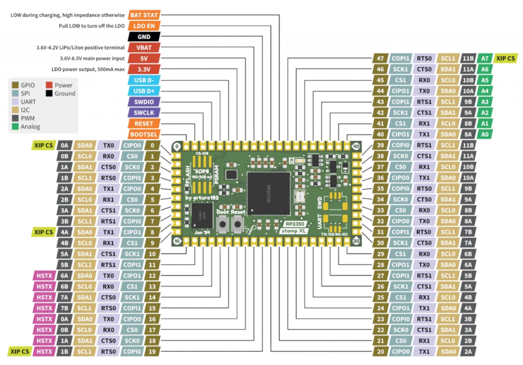
Have you seen these?  and this  Full story/pics here |
||||
| Mixtel90 Guru Joined: 05/10/2019 Location: United KingdomPosts: 6780 |
Yes. :) When I last looked Solder Party didn't seem to have a UK distributor. What the postage will be from Sweden (one of the most expensive places on the planet) I don't know. It's not available yet, apparently. I even looked at the Flexy Pins, but they seem to be out of stock in the UK. Very similar to the PGA2350 but a different arrangement. The top one is really just an "experimenter's" board for the bottom one. It's not what I'm after in this case. That module would be nice on the back of a SSD1963 though.... :) Edited 2024-08-21 01:44 by Mixtel90 Mick Zilog Inside! nascom.info for Nascom & Gemini Preliminary MMBasic docs & my PCB designs |
||||
| stanleyella Guru Joined: 25/06/2022 Location: United KingdomPosts: 2120 |
lew247 second picture could be 40 pin stripboard 20pins plus 5 each side for top and bottom...cut tracks |
||||
| Mixtel90 Guru Joined: 05/10/2019 Location: United KingdomPosts: 6780 |
Sorry, Stan. The connections are on 2mm pitch, not 2.54mm. That module is a lot smaller than you think. Mick Zilog Inside! nascom.info for Nascom & Gemini Preliminary MMBasic docs & my PCB designs |
||||
| lew247 Guru Joined: 23/12/2015 Location: United KingdomPosts: 1702 |
I did a trial quote for 8 stamps with carrier board, 5 packs of flexi pins and 2 of the flexypins breakout/adaptor board just to get a decent weight for a quote, it's actually not that bad (IF you're not in a hurry) No import duty as it's under £135  Hopefully they'll have the new XL versions in stock sometime soon. Edited 2024-08-21 17:03 by lew247 |
||||
| Mixtel90 Guru Joined: 05/10/2019 Location: United KingdomPosts: 6780 |
I must admit that when I'm doing a design I prefer to use modules that are either available from a big supplier or are in plentiful supply from a lot of sellers on AE or ebay. (It's even better to use stuff from the big component suppliers, but pointless if you don't have a business account as it costs the earth in postage charges on small orders. Then people can't afford to build your designs.) I'm unlikely to use the Solder Party modules unless I see them advertised elsewhere. At the moment they seem to be a sole supplier (well, they would be if they had any) and the other items they sell are generally no more complex than the cheap AE bits. Their shop (and only outlet)is on Tindie, which shakes my confidence a little. They are certain to be having this stuff made elsewhere, probably China. I'll hang on and see what happens. Mick Zilog Inside! nascom.info for Nascom & Gemini Preliminary MMBasic docs & my PCB designs |
||||