|

|
Forum Index : Microcontroller and PC projects : CMM2 Expansion Ports
| Author | Message | ||||
| Rickard5 Guru Joined: 31/03/2022 Location: United StatesPosts: 463 |
I was Reading another CMM2 post and there were Port Maps (I don't know the proper name) for CMM2s that look nothing like the 2 I have, I love my CMMs so much I'm scared to fiddle with GPIO Port. That's why I love the Picomites worst thing I can do is blow up $2 that I have 150 of them. My CMMs have the PIN numbers labeled but not defined, how can I find the right pin definition for each one? I may be Vulgar, but , while I'm poor, I'm Industrious, Honest, and trustworthy! I Know my Place |
||||
| Mixtel90 Guru Joined: 05/10/2019 Location: United KingdomPosts: 6783 |
It's very much like the PicoMite but the pin numbers are different - you use SETPIN to configure what you want a pin to do. The various options are shown in the manual. The layout of the GPIO port is also shown in the manual (get the right one for your CMM2 version). AFAIK the RetroMax will follow the same layout, but you will need the manual for that to be sure. The diagram shows what you can configure pins for, but they can be standard digital IO pins. For example, you could make pin 33 an input with a pullup to 3V3: SETPIN 33, DIN, PULLUP You can read it with PRINT PIN(33) so, you could set up a loop: 'this will print the value of pin 33 every 10th of a second 'use Ctrl C to stop it. SETPIN 33, DIN, PULLUP DO PRINT PIN(33) PAUSE 100 LOOP It will keep printing "1" If you now put a wire between pin 33 and GND it will print "0" while the wire is there and go back to "1" when you remove it. Mick Zilog Inside! nascom.info for Nascom & Gemini Preliminary MMBasic docs & my PCB designs |
||||
| Rickard5 Guru Joined: 31/03/2022 Location: United StatesPosts: 463 |
WOW Thanks Mick so you're saying all pins are Programable, can all Pins be 5volts ? I may be Vulgar, but , while I'm poor, I'm Industrious, Honest, and trustworthy! I Know my Place |
||||
TassyJim Guru Joined: 07/08/2011 Location: AustraliaPosts: 6098 |
NO! RTFM VK7JH MMedit MMBasic Help |
||||
| Rickard5 Guru Joined: 31/03/2022 Location: United StatesPosts: 463 |
@ TassyJim I can't find the Manual otherwise I would read it, I get ton's of errors on Gizmo's website Rick I may be Vulgar, but , while I'm poor, I'm Industrious, Honest, and trustworthy! I Know my Place |
||||
| phil99 Guru Joined: 11/02/2018 Location: AustraliaPosts: 2135 |
Try https://geoffg.net/maximite.html , the downloads are at the bottom of the page. PS, If you are having trouble accessing Geoff's site perhaps the browser or OS security settings are the the problem. See if you can create an exception for that site in the settings. Or try another browser. Edited 2024-07-11 15:23 by phil99 |
||||
| Mixtel90 Guru Joined: 05/10/2019 Location: United KingdomPosts: 6783 |
Try the Brave browser. It's pretty nippy and I've had no problems with it on any web sites. I did have problems with Firefox on some sites. The 5V pins are the ones marked 5V in the manual. Mick Zilog Inside! nascom.info for Nascom & Gemini Preliminary MMBasic docs & my PCB designs |
||||
Quazee137 Guru Joined: 07/08/2016 Location: United StatesPosts: 567 |
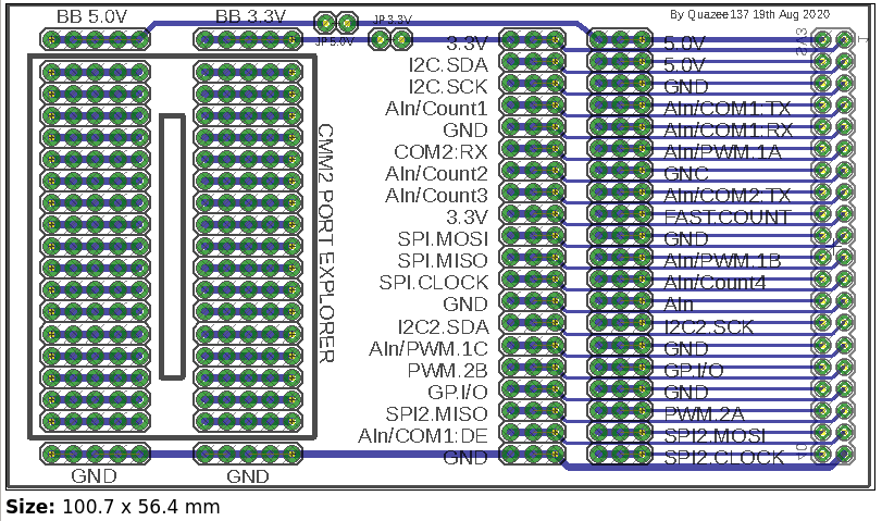
Rickard5 A while back I made this for a school TBS I have more if you want one. I think I may have the full kits. Quazee137 |
||||
| Volhout Guru Joined: 05/03/2018 Location: NetherlandsPosts: 4223 |
Hi Quazee137, For what version of the CMM2 are these. I seem to remeber that the original connector (on the CMM2G1) was upside down. And that was changed at the CMM2G2. And if recall right, the latest incarnation CMM2G2V2 is back to G1 pinout. I guess this is made in the high days of the CMM2, so for the G1..?? Regards, Volhout Edited 2024-07-11 20:45 by Volhout PicomiteVGA PETSCII ROBOTS |
||||
Quazee137 Guru Joined: 07/08/2016 Location: United StatesPosts: 567 |
Volhout Yes it is for CMM2G1. I also used it on a RPi Zero  Quazee137 Oh also a few of these 170Hatstand |
||||
| lizby Guru Joined: 17/05/2016 Location: United StatesPosts: 3150 |
I bought one of Quazee's cmm2 breadboards 4 years ago. Worked perfectly. Very Useful. Also useful have been bigmik's CMM2 header breakout boards: (Big) Mick's CMM2 Breakout PCBs ~ Edited 2024-07-13 00:08 by lizby PicoMite, Armmite F4, SensorKits, MMBasic Hardware, Games, etc. on fruitoftheshed |
||||
Quazee137 Guru Joined: 07/08/2016 Location: United StatesPosts: 567 |
Sadly its going away. It works great for many projects that use the RPi 40 pin buss. last chance :( I have used around 25 of these for my MM170 Hatstand based controllers making use of a few RPi hats and my own pcbs. Quazee137 |
||||