|

|
Forum Index : Microcontroller and PC projects : my very simple PWM problem
| Page 1 of 2 |
|||||
| Author | Message | ||||
| DaveJacko Regular Member Joined: 25/07/2019 Location: United KingdomPosts: 76 |
I can't get this 2-line program to work, it must be me, it usually is... setpin gp4,pwm2A PWM 2,1000,50,0 'reports error pin not set for PWM |
||||
TassyJim Guru Joined: 07/08/2011 Location: AustraliaPosts: 6098 |
You have one pin set but the second line is trying to set the duty for two pins. Try with PWM 2,1000,50 Jim VK7JH MMedit MMBasic Help |
||||
| matherp Guru Joined: 11/12/2012 Location: United KingdomPosts: 9110 |
You are setting a valid duty cycle (0) for a pin you haven't set as a PWM output Try PWM 2,1000,50 |
||||
| phil99 Guru Joined: 11/02/2018 Location: AustraliaPosts: 2135 |
As channel 2B has no "Setpin gp5,pwm2B" try omitting it from the PWM command. setpin gp4,pwm2A PWM 2,1000,50 Edit. Too slow. Edited 2024-07-02 07:51 by phil99 |
||||
| DaveJacko Regular Member Joined: 25/07/2019 Location: United KingdomPosts: 76 |
thanks, guys! .. solved problem ! Jim, Peter, Phil I'm just playing with a 1930's Bakelite micro-Ammeter I collect these old things, I like how a milliAmp from a pico can move a needle from the 1930's |
||||
| Rickard5 Guru Joined: 31/03/2022 Location: United StatesPosts: 463 |
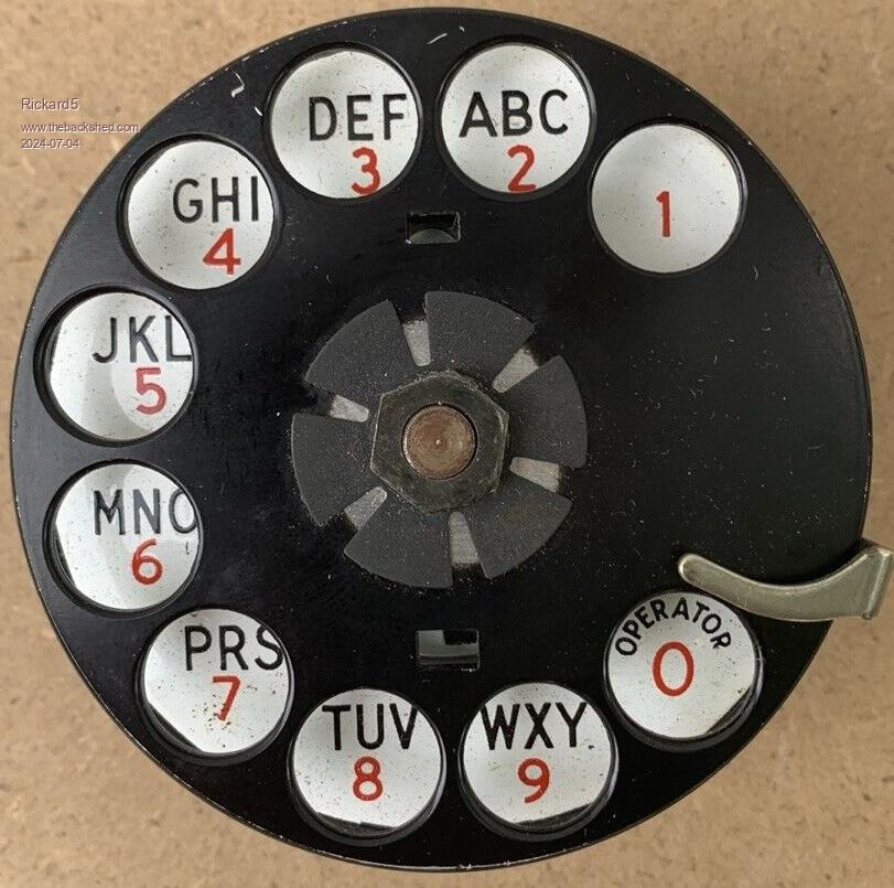
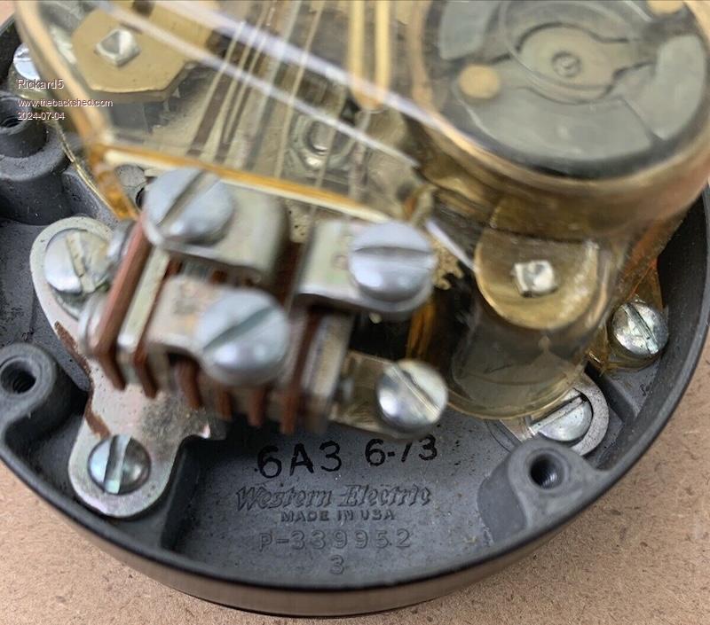
Dave I'm watching a Western Electric Black Rotary Dialer I Want Badly to acquire, and build a very Steam Punk Calculator with MMBasic on the Pico Use th dial as a number psd and a Button matrix for operator buttons:) the hard part is how to use 8 segment LEDs for Displays. and I'd love to have a pull arm or a carriage line feed that ratchets on top as the enter Key as it would be a Reverse Polish Calculator! Something Very Brazil!   I may be Vulgar, but , while I'm poor, I'm Industrious, Honest, and trustworthy! I Know my Place |
||||
| Mixtel90 Guru Joined: 05/10/2019 Location: United KingdomPosts: 6783 |
7 (8 if you count the decimal point) segment displays are pretty easy to do. I wrote some GCBASIC routines ages ago to use a PIC chip as a driver for a 4-digit display. You put the number to be displayed into a buffer. Then it's a lookup table to see which segments to light for the digit being handled at the time. You just keep stepping round the digits doing that. If you make each digit step on a SETTICK interrupt then all you need to do is write to the buffer, the interrupt will do everything else automatically. Mick Zilog Inside! nascom.info for Nascom & Gemini Preliminary MMBasic docs & my PCB designs |
||||
| Volhout Guru Joined: 05/03/2018 Location: NetherlandsPosts: 4223 |
Rickard, TM1637(4 digit) and TM1638(8 digit) LED display modules are cheap, and people have connected them to PicoMite before. Volhout PicomiteVGA PETSCII ROBOTS |
||||
| DaveJacko Regular Member Joined: 25/07/2019 Location: United KingdomPosts: 76 |
Superb project, Rickard ! I have used the TM1637 etc with the uMite, easy and nicely retro. However, I cannot get them to work with Pico.. very frustrated. Same program, same timings, but the wrong segments light up. I'll have a look around the backshed for a solution. (and I'll also google the Brazil reference !) Would like to use Nixies but expensive. |
||||
palcal Guru Joined: 12/10/2011 Location: AustraliaPosts: 1873 |
@ DaveJacko, Did you get a clock to work with the MM and TM1637. I tried using Matherp's code HERE I had no luck same with PicoMite. "It is better to be ignorant and ask a stupid question than to be plain Stupid and not ask at all" |
||||
| DaveJacko Regular Member Joined: 25/07/2019 Location: United KingdomPosts: 76 |
yes Palcal, TM1637 works with MM, don't with Picomite, spent hours on it. now gone off to play with HC-12/Pico zero/multicolor led for a while regs Dave |
||||
palcal Guru Joined: 12/10/2011 Location: AustraliaPosts: 1873 |
Did you use Peter'e code or your own. If your own can you post it here. Mine works with Peter's code for about a minute and then just flicks random numbers all over the screen. I'm using 28 pin with appropriate changes to pin nos. Peter used a 44 Pin don't know if that makes a difference. Now it has stopped altogether, screen blank. Maybe faulty screen Edited 2024-07-05 14:16 by palcal "It is better to be ignorant and ask a stupid question than to be plain Stupid and not ask at all" |
||||
| Mixtel90 Guru Joined: 05/10/2019 Location: United KingdomPosts: 6783 |
I don't know this chip at all, but if it's a timing issue how are you driving it? I've just looked it up. It could be that it needs accurate timing, in which case you may need to use BITBANG BITSTREAM on the Pico. It's a pity it isn't standard I2C. Mick Zilog Inside! nascom.info for Nascom & Gemini Preliminary MMBasic docs & my PCB designs |
||||
palcal Guru Joined: 12/10/2011 Location: AustraliaPosts: 1873 |
Peter published the original code back in 2016 Here I'm wanting to make a small clock I can run from a battery. "It is better to be ignorant and ask a stupid question than to be plain Stupid and not ask at all" |
||||
| DaveJacko Regular Member Joined: 25/07/2019 Location: United KingdomPosts: 76 |
I don't believe it needs accurate timing, I've tried with a pause 0.1 after every every level change, ( clk and dat, up or down ), pico versions just light the wrong segments, same wrong segments every time. Palcal.. I've attached my code (inspired by Peter) for the Micromite, works fine, no delays per se so probs way too fast.. ' Clock demo 7 seg driver ' ok with pic pullup ' Dave J 2020 Option autorun on dat=18 'pinout clk=17 init mnlp: Pause 500 colon=colon Xor &H80 start wrtb(&H40) 'comm1 stop start wrtb(&HC0) 'comm2 wrtb(dgt%(Asc(Mid$(Time$,4,1))-48)) wrtb(dgt%(Asc(Mid$(Time$,5,1))-48)Or colon) wrtb(dgt%(Asc(Mid$(Time$,7,1))-48)) wrtb(dgt%(Asc(Mid$(Time$,8,1))-48)) stop GoTo mnlp '------------------- subs Sub wrtb(b As integer) '--- write byte tb=b For i=0 To 7 SetPin clk,dout 'clk lo If (tb And 1) Then 'set bit SetPin dat,din Else SetPin dat,dout EndIf SetPin clk, din 'clk hi tb= tb >> 1 Next i SetPin clk, dout 'clk lo SetPin dat, din 'release dat SetPin clk, din 'clk hi 'check ack here? SetPin clk, dout 'clk lo End Sub Sub start '-------- start SetPin dat,dout 'dat lo End Sub Sub stop '--- stop SetPin dat, dout 'dat lo SetPin clk, din ' clk hi ' SetPin dat, din ' dat hi End Sub Sub init '---- initialise TM1637 Pin(dat)=0 Pin(clk)=0 SetPin dat,din,pullup SetPin clk,din,pullup Dim dgt%(9)=(&H3F,&H06,&H5B,&H4F,&H66,&H6D,&H7D,&H07,&H7F,&H6F) ' ,&H77,&H7C,&H39,&H5E,&H79,&H71) 'A..F ' degree symbol is &H63, C is &H39 ' colon - or 2nd digit with &H80 start 'reset, enab(8)+brightness wrtb(&H80+8+7) '0=dim stop End Sub |
||||
| Mixtel90 Guru Joined: 05/10/2019 Location: United KingdomPosts: 6783 |
If it's a case of the timing being fine but getting thr wrong segments then you have to be shifting them out incorrectly. Are you sending active low instead of active high or something? Possibly clocking twice at the beginning so it throws everything out by one segment? Mick Zilog Inside! nascom.info for Nascom & Gemini Preliminary MMBasic docs & my PCB designs |
||||
palcal Guru Joined: 12/10/2011 Location: AustraliaPosts: 1873 |
Thanks for that Dave, it ran with minutes and seconds so I changed it to hours and minutes, working fine. Peter's code runs for about a minute then dislays random numbers very fast and stops with the number 1993? "It is better to be ignorant and ask a stupid question than to be plain Stupid and not ask at all" |
||||
palcal Guru Joined: 12/10/2011 Location: AustraliaPosts: 1873 |
@DaveJacko Still running Ok. Wondering if there is a reason you used wrtb(dgt%(Asc(Mid$(Time$,4,1))-48)) instead of wrtb(dgt%(Val(Mid$(Time$,4,1)))) I tried to eliminate the leading zero but had no luck. "It is better to be ignorant and ask a stupid question than to be plain Stupid and not ask at all" |
||||
| DaveJacko Regular Member Joined: 25/07/2019 Location: United KingdomPosts: 76 |
probably because I still think in assembly language  also why I use the shrtst variable names I can  best regards ! |
||||
| Mixtel90 Guru Joined: 05/10/2019 Location: United KingdomPosts: 6783 |
nt a _prb  Mick Zilog Inside! nascom.info for Nascom & Gemini Preliminary MMBasic docs & my PCB designs |
||||
| Page 1 of 2 |
|||||