|

|
Forum Index : Microcontroller and PC projects : Pineapple Pi-Mite VGA revisited
| Author | Message | ||||
| Mixtel90 Guru Joined: 05/10/2019 Location: United KingdomPosts: 6783 |
I was never completely happy with this design. It wasn't *quite* mechanically close enough to a Raspberry Pi for me. So the other day I decided to redo it in a USB version. After several aborted attempts this is the result. It has no electronic compatibility whatsoever with the Raspberry Pi and doesn't pretend to have. Going clockwise from the SD card: Similar push-push uSD socket in the same position. Reset button (only needed for Pico module). Not an option on the Pi 3B. GPIO port is in the same mechanical position but has the middle cut out of it! VGA video, using a RJ45 connector. It's narrower than a VGA one and fits the case better. Replaces two stacked USB ports on the Pi. USB-C 5V inlet and console connection. Replaces two stacked USB ports on the Pi. RJ12 connector for multi-purpose use. Handy for I2C or COM1 connections. Pullups on all pins. Replaces the ethernet connection on the Pi. Audio output. Same position. USB-C USB / PROG. Replaces the HDMI output. Same horizontal location but height may need some case hacking. Mini USB 5V inlet. Replaces a micro USB (i.e. unsolderable version) on the Pi. The board is designed round the YD-RP2040 to give additional flash space and all four ADC channels (although these are not enabled as such by default). This module needs a minor mod to enable it to power USB devices. Both this and the CH9340C USB/TTL converter are available very cheaply from AliExpress. As usual bits of this design can be omitted if you don't need them. There isn't a lot that is mandatory! The YD-RP2040, by default, provides you with GP26-GP29 and GP23 all set up as normal digital GPIO pins. The 16MB flash versions that I have are restricted to 252MHz, but apparently the 4MB flash versions will run right up to 378MHz, which might be useful as we are using a DAC for audio, which puts a bit of extra strain on the hardware. Here's a circuit diagram for those who are interested in such things: Pineapple Pi-mite 4.1 circuit.pdf Mick Zilog Inside! nascom.info for Nascom & Gemini Preliminary MMBasic docs & my PCB designs |
||||
| PhenixRising Guru Joined: 07/11/2023 Location: United KingdomPosts: 857 |
Oh, very nice. Those RPi enclosures are very professional-looking. Packaging is very important for me. Not crazy about the CR1220 though. I just received a CR123 carrier which I would mount to the enclosure itself and have a couple of wires running to a header on the board. Thinking that the CR123 could last maybe 10 years (?) |
||||
| Mixtel90 Guru Joined: 05/10/2019 Location: United KingdomPosts: 6783 |
I was a bit short of space for a battery. :) The tiny RTC has its own anyway. The CR1220 is only there just in case you want to recycle the RTC module instead of throwing it away. ---------- Also: On the RJ12, GP2 and GP3 are on system I2C so a simple adapter can be made from a 4-core phone/modem lead and a WII extension to connect to a WII controller. If C7 is a disc ceramic it can be folded flat onto the PCB and the YD-RP2040 mounted much lower by soldering its headers directly to the PCB. The VGA over RJ-45 should, in theory, be compatible with the cheap adapters that are available. No need for soldering or cable chopping. I actually wanted sockets with the tab at the top but they are much harder to find in RJ-45. Common for RJ-12 though. The audio output is easily enough to drive highish impedance headphones with no further amplification. The mini USB is there because I have some. :) Mick Zilog Inside! nascom.info for Nascom & Gemini Preliminary MMBasic docs & my PCB designs |
||||
| PhenixRising Guru Joined: 07/11/2023 Location: United KingdomPosts: 857 |
Heck another thing I'd never heard of....RJ45 to VGA...Perfect solution  |
||||
| Mixtel90 Guru Joined: 05/10/2019 Location: United KingdomPosts: 6783 |
It's not ideal as CAT5 is 100R impedance and VGA is 75R, but in reality it seems to work fine up to 800x600 displays over couple of metres. However, the connectors are easy to get and take up less PCB area. With a cheap crimping tool you can make custom length leads very easily. The CAT5 lead is actually a standard non-crossover ethernet one, there's nothing special about it. Mick Zilog Inside! nascom.info for Nascom & Gemini Preliminary MMBasic docs & my PCB designs |
||||
| PhenixRising Guru Joined: 07/11/2023 Location: United KingdomPosts: 857 |
Mick, do you have a link or image re:enclosure? |
||||
| Mixtel90 Guru Joined: 05/10/2019 Location: United KingdomPosts: 6783 |
Nope. I worked from a dimensioned drawing of the PCB that I found here, on the web If the dimensions of the board are correct then any model 3B enclosure should fit. However, it *isn't* a Raspberry pi and there definitely will be differences. In particular, the cases made from stacked layers will need to have lumps cut out from every layer as they are designed to wrap round the components on the inside. So, not all cases will fit, some will probably fit well and others will need only a bit of modification (especially where the VGA socket is). Mick Zilog Inside! nascom.info for Nascom & Gemini Preliminary MMBasic docs & my PCB designs |
||||
| PhenixRising Guru Joined: 07/11/2023 Location: United KingdomPosts: 857 |
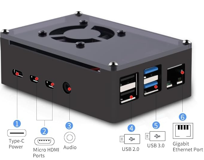
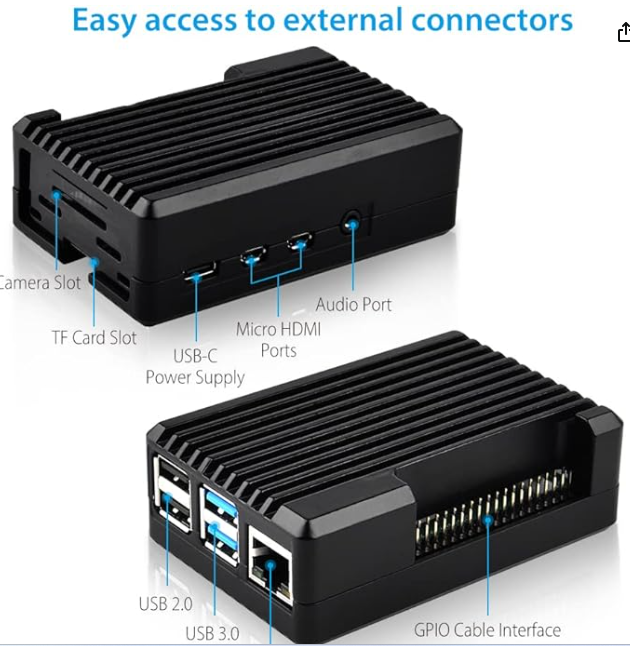
So I grabbed a couple of enclosures and yeah, these things look really tidy, good call  One is fan cooled and the other is like one big heat-sink. I plan to use the fan-cooled model but probably lose the fan. The heat-sink version requires making contact with the MCU and in my case, I'd need to mill some material off it which I don't wanna get into. Should look quite professional when I'm done  |
||||
| PhenixRising Guru Joined: 07/11/2023 Location: United KingdomPosts: 857 |
  |
||||
| Mixtel90 Guru Joined: 05/10/2019 Location: United KingdomPosts: 6783 |
For my design both cases will need quite a bit of work. The heatsink type will probably need the internal heatsink bit cutting off completely (I'd probably use an angle grinder or a Dremel if I can't get that in) and the fan type will need the fan removing. After that it's a case of opening up the side holes where necessary. Mick Zilog Inside! nascom.info for Nascom & Gemini Preliminary MMBasic docs & my PCB designs |
||||