|

|
Forum Index : Microcontroller and PC projects : Picomite VGA SDCard Fail
| Author | Message | ||||
| Rickard5 Guru Joined: 31/03/2022 Location: United StatesPosts: 463 |
I'm on a building kick right now , and I just finished 3 design 1 Picomite VGAs and all 3 have the same problem, the SD Card doesn't work :( I flashed them with PicomiteVGA MMBasic Version 5.07.06, because for some reason I can not reach geoffg.net from any machine on my network. I set the option to "option SDCARD GP13,GP10,Gp11,GP12" and when I do files on a Scared that is full of Picomite and CMM Files I Get Back the following >files\ A:/ <dir> . <dir> .. 00:00 01-01-2000. 4 boot count 2 directories, 1 file I for the life don't know what I did wrong, can any one help please Thanks Rickard I may be Vulgar, but , while I'm poor, I'm Industrious, Honest, and trustworthy! I Know my Place |
||||
| v.lenzer Regular Member Joined: 04/05/2024 Location: GermanyPosts: 49 |
What happens if You change to drive B: ? Is the SD-card ready? Best wishes! Joachim |
||||
| Rickard5 Guru Joined: 31/03/2022 Location: United StatesPosts: 463 |
how do I change to B:? I may be Vulgar, but , while I'm poor, I'm Industrious, Honest, and trustworthy! I Know my Place |
||||
| phil99 Guru Joined: 11/02/2018 Location: AustraliaPosts: 2135 |
The Pico firmware creates Drive A: in the on-board flash chip so as noted above the SD card is B:. Here is PicoMite V5.09.00RC5 firmware. PicoMite_Beta (1).zip Edit. At the command prompt type B: <enter> Edited 2024-06-28 16:18 by phil99 |
||||
| v.lenzer Regular Member Joined: 04/05/2024 Location: GermanyPosts: 49 |
on the console "B:" in the program "DRIVE B:". For more details see the manual from page 19 (last paragraph) and page 70. Good luck! Best wishes! Joachim |
||||
| Rickard5 Guru Joined: 31/03/2022 Location: United StatesPosts: 463 |
Thanks Phil for posting the firmware where I could get it :) <3 I may be Vulgar, but , while I'm poor, I'm Industrious, Honest, and trustworthy! I Know my Place |
||||
| Rickard5 Guru Joined: 31/03/2022 Location: United StatesPosts: 463 |
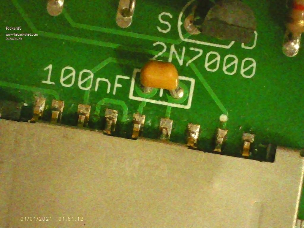
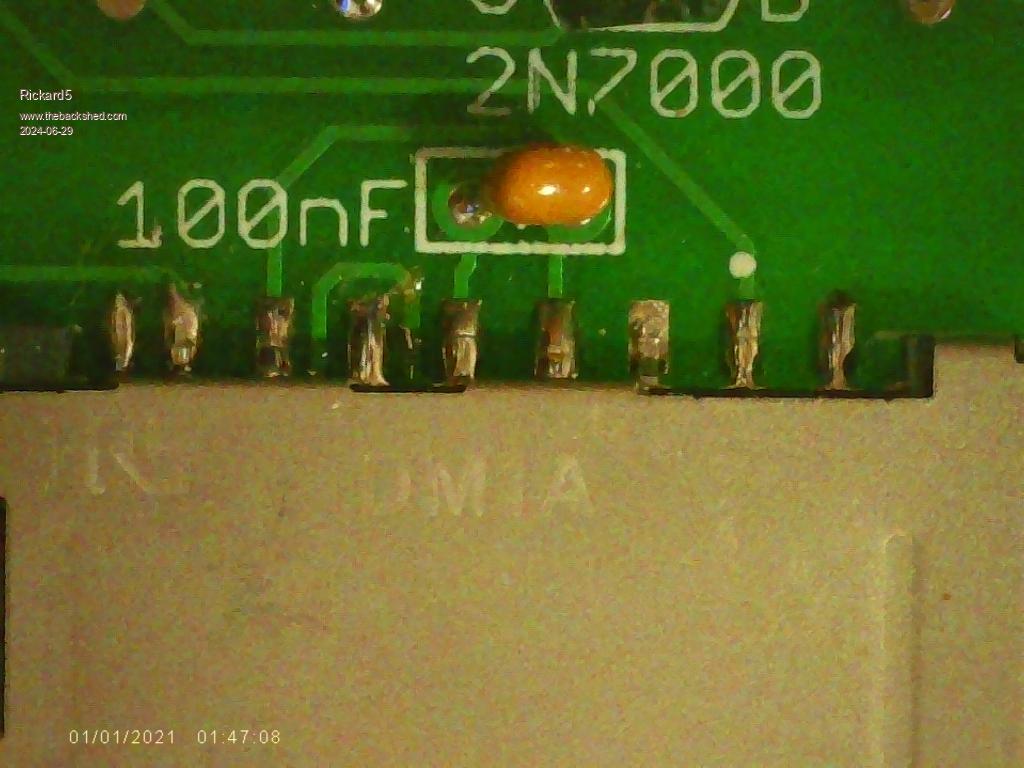
I've re-flashed all board and No joy Tried to Change to B: from prompt and I get the same results below is pictures of the solder job on 2 of the boards and I've checked all other solder joint under micro scope too   I may be Vulgar, but , while I'm poor, I'm Industrious, Honest, and trustworthy! I Know my Place |
||||
| phil99 Guru Joined: 11/02/2018 Location: AustraliaPosts: 2135 |
Same settings as I use on PicoMiteVGA MMBasic Version 5.09.00RC5 without problem. "Option List" will show if the option has been accepted correctly. That just leaves the hardware. Check that you have 3.3V across the 100nF cap. Others have found some SD cards can be fussy about the supply impedance so add a 10µF SMD ceramic across the 100nF if no cards work at all. Check continuity from each SD pin to the top of the Pico pins, as per the diagram in the manual (p18 in the most recent one) in case there is bad contact in the Pico socket. Another possibility is poor contact in the SD socket. Look inside with a magnifying glass for an out of place contact. Some masking tape on the top of the card, at the contact end may press it down on the contacts better. Edited 2024-06-29 14:28 by phil99 |
||||
| Mixtel90 Guru Joined: 05/10/2019 Location: United KingdomPosts: 6783 |
What do you mean, you get the same result? I've just done this using 5.08.00 on a PicoMite VGA. The .... is the directory and files counts. > files A:/ <DIR> . <DIR> .. ..... > b: > files B:/ <DIR> test <DIR> test1 .... > If you get "SD card not found" when you get to > b: > files then your card hasn't been recognised. MicroSD cards are generally a lot less troublesome. You could try a micro size in an adapter. A 100nF on the 3V3 rail is usually enough to tame these. Full size SD cards can be very mixed. I had a couple that would work fine in a PC and CMM2 but not in a Pico at one time. If there is no electrolytic on the card supply rail then I would definitely add one if it's a full size card. Generally I go for 22uF, but that's because I usually find those first. I prefer to use a normal electrolytic here as they are cheap and easy to fit. the SMD types are neat but fiddly. Sometimes I use tantalum electrolytic - it depends on what I last found in my stash. :) I'd suggest that you need 10uF as an absolute minimum as some SD cards can draw quite big spikes in write mode. Edited 2024-06-29 17:32 by Mixtel90 Mick Zilog Inside! nascom.info for Nascom & Gemini Preliminary MMBasic docs & my PCB designs |
||||
| Rickard5 Guru Joined: 31/03/2022 Location: United StatesPosts: 463 |
@ Mick I've refreshed all 3 picomite VGA boards I finished and am now using a 2 gig microSD Card in an Adaptor. please excuse the bad screen capture but this is what I get from all 3 boards Please excuse the LOW TEK Screen Capture Thank You I may be Vulgar, but , while I'm poor, I'm Industrious, Honest, and trustworthy! I Know my Place |
||||
| Mixtel90 Guru Joined: 05/10/2019 Location: United KingdomPosts: 6783 |
How is your card formatted? If you do it on Windows the default format may be wrong. It won't work with NTFS. Your options are correct for that board and we know that the board design is ok so it must be something else. We need to check for bad etches and bad connections. With the card removed and the power off, preferably with the Pico unplugged, check for shorts and/or open circuit connections from the Pico socket to the SD card socket. Use a thin wire into the socket so that you are checking the soldered joints. It looks like the SD card isn't even attempting to be accessed. Note that MMBasic is currently at 5.08 on Geoff's site. It would be worth upgrading. Mick Zilog Inside! nascom.info for Nascom & Gemini Preliminary MMBasic docs & my PCB designs |
||||
| Volhout Guru Joined: 05/03/2018 Location: NetherlandsPosts: 4223 |
What is a “design 1 VGA”? Is this matching the pin definition in the OPTION SDCARD Volhout PicomiteVGA PETSCII ROBOTS |
||||
| Mixtel90 Guru Joined: 05/10/2019 Location: United KingdomPosts: 6783 |
The board design is the one listed on Geoff's site as Design #1. The pin definitions are ok for that. Mick Zilog Inside! nascom.info for Nascom & Gemini Preliminary MMBasic docs & my PCB designs |
||||
| matherp Guru Joined: 11/12/2012 Location: United KingdomPosts: 9110 |
Use RC5 and set up the board with OPTION RESET VGA DESIGN 1 Then insert a card and type FILES "B:/*.*" If that doesn't work you have a H/W problem you will need to track down |
||||
| Rickard5 Guru Joined: 31/03/2022 Location: United StatesPosts: 463 |
Matherp, tried the reset Got it down to it has to be HW, after resetting the board I finely got a SD Card not ready msg so that is forward motion, but I did try several SD and Micro SD cards, and one TF Card. so I'm gonna Guess either the SD Card Sockets are wrong or the Cap is wrong, there is nothing between ? I may be Vulgar, but , while I'm poor, I'm Industrious, Honest, and trustworthy! I Know my Place |
||||
| Mixtel90 Guru Joined: 05/10/2019 Location: United KingdomPosts: 6783 |
Do those continuity and shorts tests, Rick. That's the first step. If they are all ok then put the Pico back and check continuity of each of the GP pins to the SD card socket. It wouldn't be the first time that Pico socket strip had been faulty, but it's rare. I'll be surprised if the SD card sockets are faulty on all three boards. The only faulty ones I've had have been that way after I broke them. :) Have you got a blank PCB that you can also check for continuity on those traces? Mick Zilog Inside! nascom.info for Nascom & Gemini Preliminary MMBasic docs & my PCB designs |
||||
| matherp Guru Joined: 11/12/2012 Location: United KingdomPosts: 9110 |
One failure mode when assembling SD sockets is to allow them to sit up off the PCB on the solder even though the connection to the pins is good.. Never tin the pads before fitting the socket. It must fit tightly down on the board as it is this fit that holds the card against the contacts |
||||
| Volhout Guru Joined: 05/03/2018 Location: NetherlandsPosts: 4223 |
Rickard5, To much solder may short out the pins to the metal. Your second photo shows potential candidates for these shorts. Can easilly be detected with a multimeter. The first photo has a non-soldered pin (6'th from the left). Volhout PicomiteVGA PETSCII ROBOTS |
||||
| Mixtel90 Guru Joined: 05/10/2019 Location: United KingdomPosts: 6783 |
It might be an idea to lift some of the solder off using fine solder wick. First, it will remove any excess solder, secondly the re-heating and pressure will help the remaining solder get between the contact and the trace to improve the contact. You can always put solder back if you need to. :) Mick Zilog Inside! nascom.info for Nascom & Gemini Preliminary MMBasic docs & my PCB designs |
||||