
|
|
Forum Index : Microcontroller and PC projects : RPZ Compute module
| Page 1 of 4 |
|||||
| Author | Message | ||||
| Mixtel90 Guru Joined: 05/10/2019 Location: United KingdomPosts: 8913 |
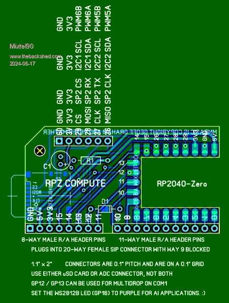 This is breadboard (and stripboard) friendly. It only needs a 20-way female SIP socket to plug it into. If you block way 9 you can easily see if it's in backwards. I think it's pretty self-explanatory. It's obviously intended as an embedded control module, but it's easy to reprogram and move around. It could be mounted horizontally, and fastened down with the fixing hole, but it's probably a bit of a waste. Cheap to build and every (normal) pin of the Zero (which is surface mounted) is made available. Once again, I'll produce gerbers if anyone is interested. . Edited 2024-06-17 08:03 by Mixtel90 Mick Zilog Inside! nascom.info for Nascom & Gemini Preliminary MMBasic docs & my PCB designs |
||||
| v.lenzer Senior Member Joined: 04/05/2024 Location: GermanyPosts: 117 |
Hello Mick! I'm interested in your PCB and would like to have the Gerber file. If you worked with Sprintlayout, the Sprintlayout file would be enough for me. I couldn't find the files in your Dropbox. Thank you very much in advance! Best wishes! Joachim |
||||
| Mixtel90 Guru Joined: 05/10/2019 Location: United KingdomPosts: 8913 |
I've not put it in Dropbox. To be honest, I'd expected more interest in this as it allows a PicoMite to be mounted in a small area very easily, yet still be removable without having to lever it out. :) Perhaps surface mounting makes people unhappy. :) For embedded stuff the uSD card probably isn't needed, and the four extra IO pins would be useful. Here's a Zip with both the SL6 and the Gerbers: RPZ compute module.zip Mick Zilog Inside! nascom.info for Nascom & Gemini Preliminary MMBasic docs & my PCB designs |
||||
| v.lenzer Senior Member Joined: 04/05/2024 Location: GermanyPosts: 117 |
Thank you, Mick! Best wishes! Joachim |
||||
| Mixtel90 Guru Joined: 05/10/2019 Location: United KingdomPosts: 8913 |
I've just been wondering... GP28 and GP29 can also be COM1, which would make that connector nice for adding a RS485 module onto. However, it clashes with GP12 and GP13 being used for multi-drop. Maybe I should move multi-drop onto GP8 and GP9 (COM2), but it's a bit awkward. I'm just playing with a little "PLC" motherboard design idea, using three of these as a master and two slaves. :) Mick Zilog Inside! nascom.info for Nascom & Gemini Preliminary MMBasic docs & my PCB designs |
||||
| Volhout Guru Joined: 05/03/2018 Location: NetherlandsPosts: 5945 |
Low cost compute module.... 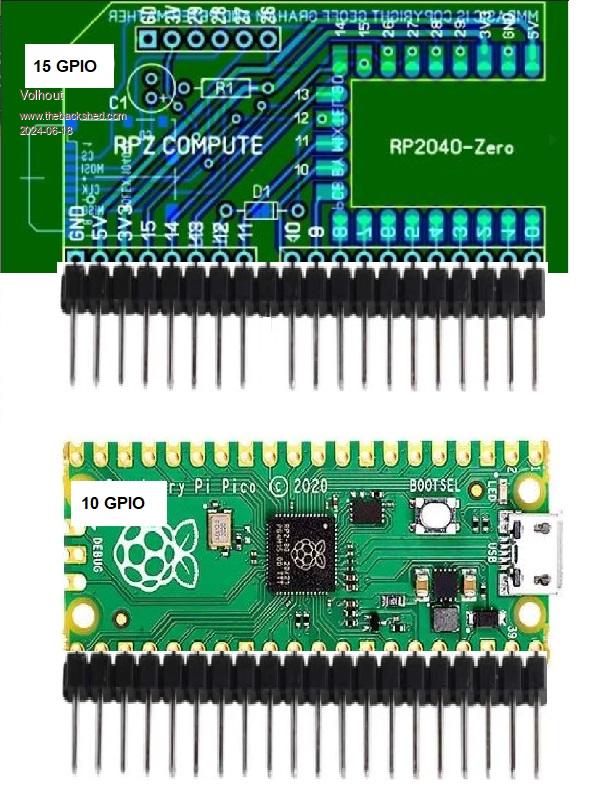 No SD card though... Volhout Edited 2024-06-18 20:43 by Volhout PicomiteVGA PETSCII ROBOTS |
||||
| Mixtel90 Guru Joined: 05/10/2019 Location: United KingdomPosts: 8913 |
Mine's more fun - and has USB-C and provision for COM port multi-drop. It also has a WS2812B and reset button. :) And the RP2040-Zero is cheaper, although you have the PCB cost. PS I can move the multi-drop to COM2. It might be worth it... Edited 2024-06-18 20:45 by Mixtel90 Mick Zilog Inside! nascom.info for Nascom & Gemini Preliminary MMBasic docs & my PCB designs |
||||
| Volhout Guru Joined: 05/03/2018 Location: NetherlandsPosts: 5945 |
Hi MIck, Yes, the zero is cheaper, just ordered 5 of them for 1 euro 80 each. But it is also 2Mb. No larger A:/ Volhout Edited 2024-06-18 23:30 by Volhout PicomiteVGA PETSCII ROBOTS |
||||
| Mixtel90 Guru Joined: 05/10/2019 Location: United KingdomPosts: 8913 |
AliExpress link Only 2MB flash. Basically it's a sawn off Pico with added Reset button and a WS2812B instead of the heartbeat LED (it doesn't flash). I've had several of them now and not found any problems in running MMBasic on them. Mick Zilog Inside! nascom.info for Nascom & Gemini Preliminary MMBasic docs & my PCB designs |
||||
| matherp Guru Joined: 11/12/2012 Location: United KingdomPosts: 11546 |
I don't understand how a 2MB flash drive can work with MMbasic. Either the flash is actually bigger than that or something very odd is going on. MMBasic firmware + program space + flash slots + option area + VAR SAVE area is > 2mb I would definitely not recommend any buying any device advertised as 2MB Edited 2024-06-19 00:46 by matherp |
||||
| Volhout Guru Joined: 05/03/2018 Location: NetherlandsPosts: 5945 |
Hi Peter, I think the original Raspberry Pi Pico is 2Mb ? Volhout PicomiteVGA PETSCII ROBOTS |
||||
| matherp Guru Joined: 11/12/2012 Location: United KingdomPosts: 11546 |
Going senile - sorry |
||||
| Mixtel90 Guru Joined: 05/10/2019 Location: United KingdomPosts: 8913 |
This version has the multidrop on COM2 (GP8 and GP9) GP28 and GP29 are now available on the ADC connector for other uses. RPZ compute module 2.0.zip Welcome to my world, Peter. ;) Mick Zilog Inside! nascom.info for Nascom & Gemini Preliminary MMBasic docs & my PCB designs |
||||
| lizby Guru Joined: 17/05/2016 Location: United StatesPosts: 3788 |
Neat. Just ordered from JLCPCB using that zip file directly. $4US via Paypal including shipping for 5 PCBs. Amazing. That's my sixth JLC order in 7 days (the other 5, my designs). Where am I going to find the time to do the soldering? PicoMite, Armmite F4, SensorKits, MMBasic Hardware, Games, etc. on FOTS |
||||
| Mixtel90 Guru Joined: 05/10/2019 Location: United KingdomPosts: 8913 |
Here's my idea for a simple multi-processor controller using the RPZ compute module. Is it the cheapest expandable PLC? :) 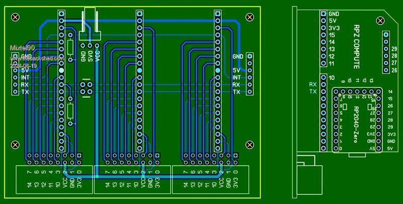 The LH socket can be configured for a normal expansion module or for the master. There can only be one master on the system and it has to be the leftmost one. The board carrying the master has the two resistors fitted and the four pads linked as a crossover. There is no expansion to the LHS for this board. Expansion boards don't have the resistors and the pads are linked straight across. Each module is powered from the 5V rail and provides its own 3V3 for its IO. A VCC pin allows an external supply to be available to the outputs. It could be used to power, say, more powerful LEDs than the IO pins can supply. It's separate from the 5V rail as it could be 12V for example. Each board has its own VCC. You could run one at 12V and another at 24V if you wish. :) The 5V supply is common to all the modules so any of them, or the rear connector, can be used for the supply. IO connections are via horizontal IDC connectors. There is a common INT line on GP15 with a pullup resistor. This is intended to be an interrupt or reset signal line - it depends on the application. Mick Zilog Inside! nascom.info for Nascom & Gemini Preliminary MMBasic docs & my PCB designs |
||||
| Volhout Guru Joined: 05/03/2018 Location: NetherlandsPosts: 5945 |
Mick, Maybe a stupid question, but why did you put the multidrop components on the compute modules? You could have placed them on the cheapest expandable PLC board. In that case you would only need one pull-up. For speed yo would want 2k on there. With 10 modules, there is 200ohm pullup when the pullups are on the compute module. Logic levels (in combination with diodes) will be hard to meet. Volhout Edited 2024-06-19 17:36 by Volhout PicomiteVGA PETSCII ROBOTS |
||||
| Volhout Guru Joined: 05/03/2018 Location: NetherlandsPosts: 5945 |
At risk of stealing the thread, I realized the pico zero would als result in the smallest VGA unit. Maybe this is already tried..? GP0..GP5 = VGA GP6,7 = AUDIO GP8,9 = PS2 GP10..13 = SD-card GP14,15 = I2C (RTC) GP14,15,26,27,28,29 expansion IO with GND,GND,5V,3.3V on a 10pin header. Volhout PicomiteVGA PETSCII ROBOTS |
||||
| Mixtel90 Guru Joined: 05/10/2019 Location: United KingdomPosts: 8913 |
There is only one pullup, on the main board - the modules only have an isolation diode on the TX pin. Putting it on there makes the main board layout easier, I think. Normally it is linked out by a solder blob pad so that the module can be used stand-alone and it becomes a normal GPIO pin. My intention is to specify a Schottky for that diode, which should help with the logic levels a lot. Small ones are cheap. As only one transmitter will go low at once the pullup could probably be reasonable - say 2k2 or 4k7. Similarly for the INT line, which is intended to function as an open collector signal. You pull it low by using SETPIN to make it an output and release it high by making it an input. There is only one pullup again. -- Ah.... Is this today's microVGA PCB challenge, Harm? :) It could have USB if you can double the PCB area. lol Mick Zilog Inside! nascom.info for Nascom & Gemini Preliminary MMBasic docs & my PCB designs |
||||
| Volhout Guru Joined: 05/03/2018 Location: NetherlandsPosts: 5945 |
No Mick, No microVGA challenge. Just something I realized. To be honest, your previous "basicVGA" design was small enough, I actually think it is a bit to small already. For some reason I like the G738 box size used for my VGA pico (and CMM2). It is compact enough for my taste, robust, and if I would ever build in a different smaller case, it would be something like your PI-3 board shape in a PI-3 (or -4) case. Again, a robust housing. Regards, Volhout PicomiteVGA PETSCII ROBOTS |
||||
| Mixtel90 Guru Joined: 05/10/2019 Location: United KingdomPosts: 8913 |
I have three new designs in the same format as the RPZ Compute. RPZ COMPUTE VGA Has a RP2040-Zero with a VGA output. Due to shortage of PCB area this uses a RJ45 socket. This works well over reasonable distances and RJ45-VGA adapters are readily available. You only need one for the monitor end. The ADC connector and GP12-GP15 are omitted. GP11 is connected to the INT signal. RPZ COMPUTE BT Has a RP2040-Zero with a HC-05 Bluetooth module connected to COM1. The ADC connector and GP11-GP14 are omitted. GP15 is connected to the INT signal. RPZ COMPUTE Y40 Has a RP2040-Zero and a JDY-40 connected to COM1. GP08 of the JDY-40 is brought out to an on-board LED. The ADC connector and GP11-GP14 are omitted. GP15 is connected to the INT signal. The JDY-40 is becoming a bit harder to find now, but there must be more than me that have a couple in a box somewhere. :) Handy for simply linking two motherboards wirelessly and cheaply. Very low current drain. Additionally, I've been playing with the original module and it's now V2.2. The GP14 pin can now be either GP14 (default) or GP26 selectable via LK2 The GP15 pin can now be either GP15 (default) or GP27 selectable via LK3 This is useful if the uSD card isn't fitted as it allows a couple of ADC inputs. A slight tweak (adding a resistor position on the motherboard) now allows I2C to be used as an alternative to multidrop COM between the modules. I considered doing a RS485 module but it's not worth it. A cheap converter has full protection and decent voltage handling. I could do one with ESP8266-01S... . Edited 2024-06-25 06:31 by Mixtel90 Mick Zilog Inside! nascom.info for Nascom & Gemini Preliminary MMBasic docs & my PCB designs |
||||
| Page 1 of 4 |
|||||
| The Back Shed's forum code is written, and hosted, in Australia. | © JAQ Software 2026 |
