
|
|
Forum Index : Microcontroller and PC projects : PicoMite PWM writing slow?
| Author | Message | ||||
| PhenixRising Guru Joined: 07/11/2023 Location: United KingdomPosts: 326 |
or am I doing something wrong? setpin gp2,pwm mcmd=50 timer=0 for i% = 1 to 1000 pwm 1,8000,mcmd next fini=timer print fini/1000 fini >1ms on 378MHz |
||||
| Volhout Guru Joined: 05/03/2018 Location: NetherlandsPosts: 3586 |
Hi Phenix, I have no idea if this is valid or not. But realize that the pico is not an Armmite H7. If you look at the benchmarks, Pico is 5x to 10x slower than H7. Peter will definitely have a better explanation, but I know there is a balance between code that runs in RAM, and code that runs from FLASH. Maybe the PWM command runs from flash. But there may be a command that updates the PWM value (not re-initialize the PWM, but just change the PMW value) that is faster. Check the user manual. Regards, Volhout Edited 2024-05-01 06:37 by Volhout PicomiteVGA PETSCII ROBOTS |
||||
| PhenixRising Guru Joined: 07/11/2023 Location: United KingdomPosts: 326 |
Granted but my rather sophisticated PID + Offset + Feedforward executes in 440µS I had this very thought; that one could simply update the duty-cycle. Looking at the manual, now. On the H7, there is little difference between writing the PWM and not writing.  My eventual output is analogue +/-10v anyway so I can easily use a 12b SPI DAC. Already been coded/tested |
||||
| matherp Guru Joined: 11/12/2012 Location: United KingdomPosts: 8604 |
Therefore you can't update the PWM in any useful fashion > 8000/second with a frequency of 8000 so your test is meaningless as the fastest that 1000 changes could be made is 1/8 of a second. |
||||
| PhenixRising Guru Joined: 07/11/2023 Location: United KingdomPosts: 326 |
Thanks Pete. No big deal, still fits in my settick 2 window. I guess I just imagined it to be something similar to dumping data into a comm's buffer but it's actually a block. Will be using a SPI DAC for the real world  |
||||
| robert.rozee Guru Joined: 31/12/2012 Location: New ZealandPosts: 2294 |
hi PhenixRising, updating time-related things (including PWM) have been discussed in the past, in order to do it without creating glitches is rather tricky. invariably it involves the interpreter waiting until a transition (or event) has happened before updating the appropriate register. as Peter has pointed out, with an 8000Hz pulse train this involves a pause of up to 1/8000th of a second before each change can be safely made. 1/8000 x 1000 = 0.125 seconds. if the interpreter's code that updates the register is clever enough, it may be able to shorten these delays by (for example) observing that if [rollover value] - [current count] is sufficiently high then the appropriate register can be updated immediately. but this being the case is pretty much indeterminate. ie, you may get 12 quick updates followed by 1 or 2 slow updates, etc. you may also see some (or many) steps effectively ignored. generally speaking, if ramping a PWM (or similar) from one value to another, you may want to pick values such that each step along the ramp is at least an order of magnitude longer than the period. so for 8000Hz (period=125uS) this might be making sure each time round the loop is 10mS long. cheers, rob :-) |
||||
| PhenixRising Guru Joined: 07/11/2023 Location: United KingdomPosts: 326 |
Thanks Rob It's just always been in my head that when considering onboard PWM vs external DAC, that the PWM would take less time to update  It's actually not a bad revelation because now I'm thinking that I might be mistaken about my ARMmite H7 project. Maybe the PWM writing is gobbling-up time and if I go with an SPI DAC, my overall loop time might be reduced. It's all good Cheers  I'll be driving these things which accept a +/-10v command input that resolves to 12bit so a I'll go with a 12bit SPI DAC.  Edited 2024-05-01 15:54 by PhenixRising |
||||
| Volhout Guru Joined: 05/03/2018 Location: NetherlandsPosts: 3586 |
Phenix, At the risk of becomming too technical, and confusing, I would like to explain a bit. 1/ PWM in essence. In a typical microcontroller peripheral, the PWM contains a counter. The counter counts clock pulses from a programmable divider. The programmable divider is programmed once (1 single register) and feeds the PWM with a continuous stream of clock pulses. The PWM also contains a compare register. When the counter value is lower than the value in the compare regsiter, the PWM output is low, when higher, the PWM output is high. Most PWM are more complicated and have far more registers, but this is the essence. Changing the PWM output is in essence changing 1 register value. This can be achieved by a single "POKE". Just to give a picture: the audio output of the picomite runs a PWM with 2 channels (2 compare regsiters for L and R) at 44.1kHz. Playing audio consumes around 20-25% CPU time at 126MHz CPU clock. This means that 2 PWM updates happen in 25% or 22us (ARM speed, not MMBasic speed). This is roughtly 2us per PWM update (including the audio conversion to PWM value). So PWM (in code) is blazing fast. But... If you want to convert the PWM output to a DC voltage, you need to apply an analog filter. Depending on how complex you make this filter (you want no ripple since that causes motor jitter) the analog filter has a built in delay. Large and complex filter can be tuned to minimal delay, and minimum ripple. Important is that simple filters (like an RC network) have delays that are directly related to the PWM frequency. So a higher PWM frequency means less delay. The audio system of the picomite can be used as an example. The 44.1kHz PWM frequency allows for roughly 11 bits resolution (lower frequencies can increase the resolution to 16 bits) and the chosen filter (LCR filter) has a sub-milisecond delay. There is however one thing that is important in using PWM. The output voltage depends on 2 paramters. The duty cycle, and the logic voltage (3.3V). When your system has a polluted 3.3V, your PWM will also be polluted. When your 3.3V drifts, your output will also drift (3.3V->+/- 10V) 6 times more. 2/ Using a DAC (MCP4822) The DAC has a different interface. It is controlled from a serial datastream. The MCP4822 DAC is controlled from SPI. Picomite has a hardware SPI controller that can send out (up to) 16 bits of data in a single MMBasic command. But the DAC does not need a low pass filter (or a very simple one). So there may be more delay in shifting the bits out, but less delay in the filter (if any). DAC's can be purchased with a variety of resolutions. The Picomite audio system uses roughly 25-30% CPU power when the MCP482x DAC is selected as audio system. Slightly more CPU load than PWM. But again, this is ARM CPU speed, not MMBasic speed. Most DAC's allow to connection of a reference voltage. This is definitely beneficial for accuracy and drift. The MCP4822 does not have this option. It has a built in reference that is not available at a pin. This is a disadvantage. Best is to use the DUAL DAC (both channels) to generate a single +/-10V output. In case the reference voltage was available at a pin the channels could be used independent. When needed I could round up some accurate numbers on delays and accuracies, but in essence the above should be sufficient to make a choice. Volhout Edited 2024-05-01 17:17 by Volhout PicomiteVGA PETSCII ROBOTS |
||||
| PhenixRising Guru Joined: 07/11/2023 Location: United KingdomPosts: 326 |
Not at all. This is good stuff This is what I was hoping for  Precisely what was going through my head Yeah, I have experience with different levels of PWM filtering and TBH, it doesn't seem to make much difference in motor control. I always end-up with a rock-steady motor shaft. The servo-drive's analogue inputs have filtering and the command signal always looks noisy anyway, due to the PID maintaining the commanded position. Really? Don't believe I ever came across this but it sounds cool Do you have a schematic? |
||||
| Volhout Guru Joined: 05/03/2018 Location: NetherlandsPosts: 3586 |
Something like this: 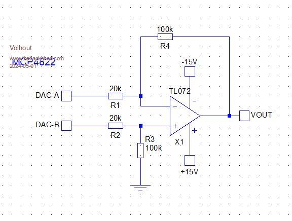 This circuit should translate 2V output of the DAC to +/- 10V. It outputs the difference between A and B. So write 4095 to A and 0 to B and you have -10V. St both to 0, or 4096, or 1999, and the output is 0. A=0 and B=4095 is +10V. Easiest is A = 4095-B Resistors must be 1% or better. Volhout Edited 2024-05-01 18:45 by Volhout PicomiteVGA PETSCII ROBOTS |
||||
| PhenixRising Guru Joined: 07/11/2023 Location: United KingdomPosts: 326 |
So instead of 20V/4096, I now get 20V/8192 (13bit effectively)? |
||||
| Volhout Guru Joined: 05/03/2018 Location: NetherlandsPosts: 3586 |
EDIT: Yes essentially you could get 13 bits. But not with A=4095-B Volhout Edited 2024-05-01 19:58 by Volhout PicomiteVGA PETSCII ROBOTS |
||||
| matherp Guru Joined: 11/12/2012 Location: United KingdomPosts: 8604 |
Just to be clear, the quoted passage I posted was from the SDK manual. Even if you poke the register the output will only change once every pwm cycle. Also you will need to do the math I do in C in Basic to calculate what to poke and you don't know the wrap count without reading that register first. |
||||
| PhenixRising Guru Joined: 07/11/2023 Location: United KingdomPosts: 326 |
Yeah, it's not an issue; the whole thing is looking fantastic Got many millions of counts through this PIO quad-decoder, driving the h-bridge with PWM: Resolution: 2_000 quadrature counts/rev Velocity: 200_000 counts/sec Acceleration: 1_000_000 counts/sec/sec Deceleration: 1_000_000 counts/sec/sec Hasn't skipped a beat You guys TOTALLY ROCK!!! |
||||
