
|

|
Forum Index : Microcontroller and PC projects : CMM2 G2 V2 design files
| Page 1 of 3 |
|||||
| Author | Message | ||||
| matherp Guru Joined: 11/12/2012 Location: United KingdomPosts: 9110 |
The CMM2 G2 V2 is designed to be much cheaper to manufacture than all previous designs. JLC can build it ready-to-run for about £133 for 5 boards (+, of course, shipping and any local taxes). It is functionally identical to the previous versions with the exception that it does not support the Hobbytronic USB mouse I/F chip. PS2 mice are still widely available and plug directly into the bottom USB socket (USB keyboard in the top). As before the Microsoft Basic Optical Mouse is highly recommended and both the V1.1A and V2.0 versions work well the the CMM2. I have 3 boxed CMM2 G2 available for sale (2 off G2 V2 and 1 off G1 V1.5) as I'm rather "over-stocked" for my development needs. Contact me by PM if interested 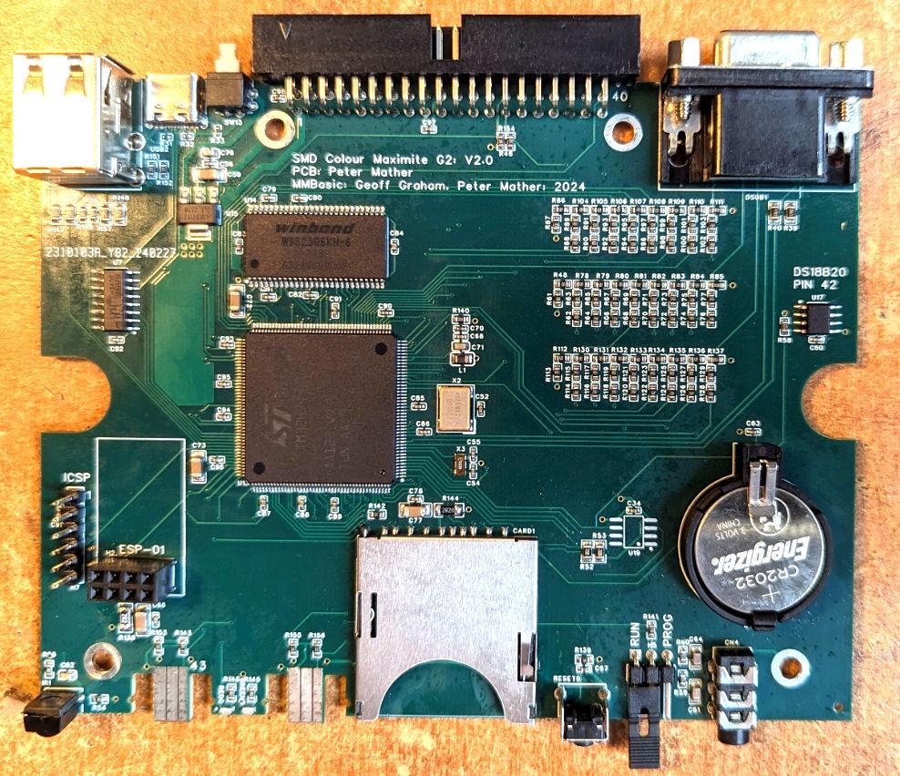   Gerbers CMM2G2V2.0.zip Bill of materials and placement files CMM2G2V2.0BOM.zip Design files for box ends: Cambam, dxf, Sketchup, stl CMM2G2V2ends.zip EasyEDA design files CMM2G2V2.zip Schematic CMM2G2V2Schematic.pdf Currently all parts are in stock at JLC 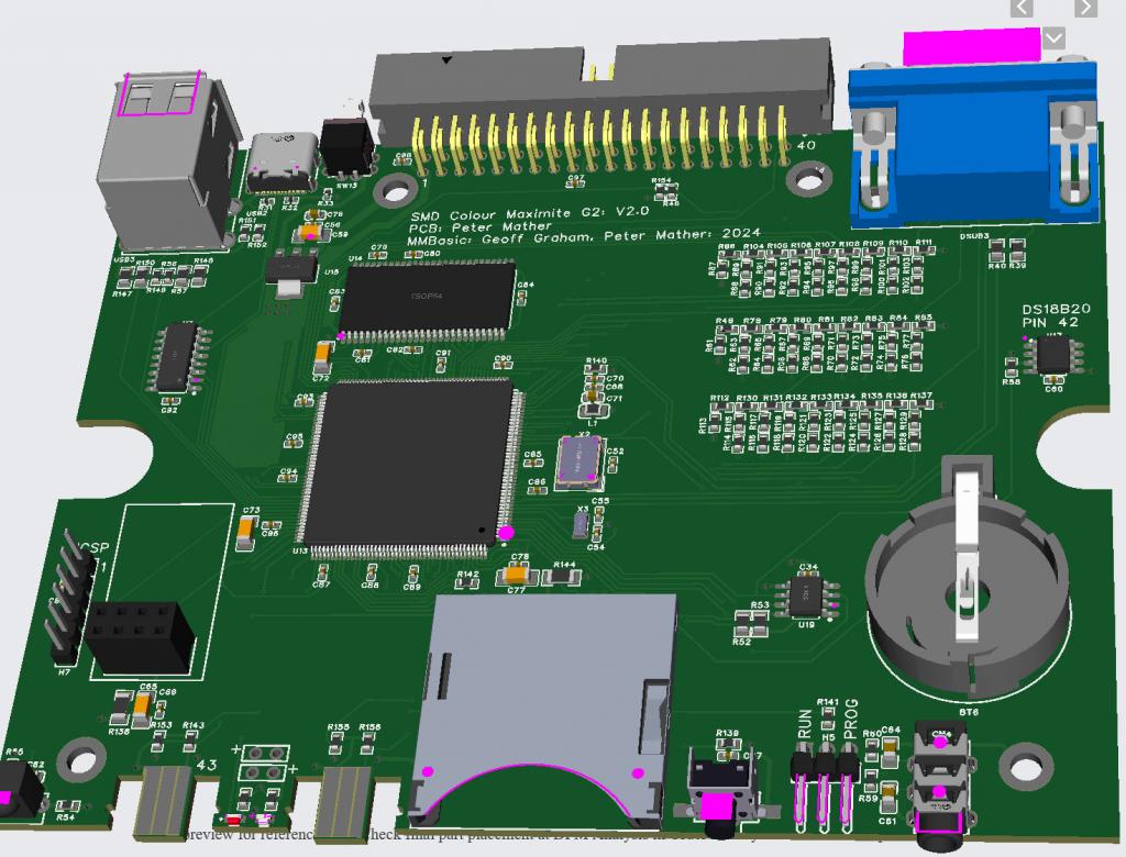 Edited 2024-04-04 21:52 by matherp |
||||
Grogster Admin Group Joined: 31/12/2012 Location: New ZealandPosts: 9306 |
Excellent, thanks Peter!  Footnote added 2024-04-05 17:19 by Grogster I will be listing these for sale on my website. As they will be much cheaper then the boards that I had to manually complete, it might really help the CMM2 become the machine it was always destined to be.  Smoke makes things work. When the smoke gets out, it stops! |
||||
| matherp Guru Joined: 11/12/2012 Location: United KingdomPosts: 9110 |
All my surplus CMM2 G2 now sold. |
||||
| joker Newbie Joined: 06/02/2024 Location: GermanyPosts: 25 |
Thumbs up also from me  This is outstanding. Thank you very much Matthias |
||||
| homa Guru Joined: 05/11/2021 Location: GermanyPosts: 351 |
I received my CMM2 yesterday. Finally I am a CMM2 owner :-) Thanks a lot Peter. Matthias |
||||
| PilotPirx Regular Member Joined: 03/11/2020 Location: GermanyPosts: 68 |
My CMM2G2V2 board has also arrived and is working perfectly. The Microsoft mouse also works perfectly. The picture is razor sharp. The system only hangs (frozen, have to reset) from time to time with subdirectories of my SD-card (which works in the old G1). I still have to test it with other SD cards. I have only noticed that the I/O pin assignment corresponds to the CMM G1 again. The 180 degree rotation of the G2 is no longer necessary. But the PIN-numbers are switched. Pin1 is now Pin 40 in schematic. How to set the Pin now? With the old system? Edited 2024-04-17 19:39 by PilotPirx |
||||
| joker Newbie Joined: 06/02/2024 Location: GermanyPosts: 25 |
Hello, I just got my oder from JLCPCB. I programmed it with the latest firmware V5.07.02b11. All five boards are working. The packageing from JLCPCB was a bit cheaper than for my first order last year, but the boards are ship shape and bristol fashion. Nothing to complain here. The first startup of the board was sometimes quite rough. Multiple resets were necessary. Mostly the keyboard was not detected in the first run. Hopefully this behaviour will go away with batteries installed. I also tried a PS2 mouse. In my first board I used the USB mouse chip but never get it working, so I was really exited to see the mouse working. And it did. Unfortunately, the interface is not very stable. After some clicks in the file explorer I got garbage on the screen and the machine finally froze. I will check this with another board later again. There is onne thing, that is suboptimal. The on/off switch is difficult to operate without an extra tool if an USB-c cable is connected. In general, I'm pretty happy with my purchase.  Best Regards Matthias |
||||
| eparmstrong Newbie Joined: 17/04/2024 Location: United StatesPosts: 2 |
First I'd like to thank Peter for making this and the PicoMiteVGA designs available. I've only managed to get 3 of the 5 boards from JLCPCB that I ordered working. Same sort of issue as joker. I'm able to program them all fine, but it seems very difficult to get them to boot the first time. Nothing will show on either the serial or VGA, and then suddenly it will start working, and once configured the first time, they continue to work fine. I'd appreciate any suggestions on how to get the initial configuration screen to show up reliably. |
||||
| homa Guru Joined: 05/11/2021 Location: GermanyPosts: 351 |
Did you recognise this in the manual? 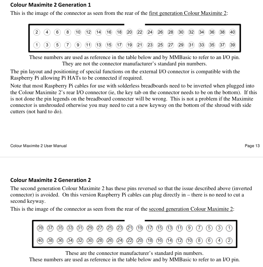 Matthias |
||||
| homa Guru Joined: 05/11/2021 Location: GermanyPosts: 351 |
Hi Matthias Shouldn't a keycap like this help? https://images.app.goo.gl/omCwqYFTLvCYfKBK6 Do you need all 5 boards or would you part with one? Just send me a PM. Gladly also in German. Matthias |
||||
| PilotPirx Regular Member Joined: 03/11/2020 Location: GermanyPosts: 68 |
The pin assignment is not as printed on the board. If you look on the back, pin 40 is upper right (where the arrow is)and pin 1 is down left. I measured this with a voltmeter- its like first Gen CMM2. But the print on the board is vice versa. And Pin40 in the schematic was previously Pin 1. Here the new pinning and here the old one: same functions, but pin numbers switched Edited 2024-04-19 18:02 by PilotPirx |
||||
| homa Guru Joined: 05/11/2021 Location: GermanyPosts: 351 |
@peter: Can you clarify this? I am now totally confused. Since I have the CMM2 Gen2 as V1.5, a new change would bother me now :-( I'm also thinking about getting one of the new boards from Matthias (@matthias: I'll get back to you after I hear back here). Matthias |
||||
| matherp Guru Joined: 11/12/2012 Location: United KingdomPosts: 9110 |
Sorry about the confusion. The boards made from the gerbers published on this thread should have the same pinout as the 1.5 G2 The two G2V2 development boards sold to PilotPirx and stoke_ferry had the G1 pinout as a result of me copying the wrong layout. I had forgotten I made this change between the prototype G2V2 and the final version as above and should have communicated this to the two recipients |
||||
| homa Guru Joined: 05/11/2021 Location: GermanyPosts: 351 |
Thank you for the clarification.  |
||||
| stoke_ferry Newbie Joined: 26/04/2023 Location: United KingdomPosts: 3 |
Thanks Peter, and noted. Apart from checking it works I haven't used the CMMG2V2 yet. Stuart |
||||
| homa Guru Joined: 05/11/2021 Location: GermanyPosts: 351 |
Hi Peter, Another question about the CMM2 enclosures. Where can you buy them in Europe? I only found one source in Australia. But shipping is too expensive for me. Do you have 3D print files for them? Kind regards Matthias |
||||
| matherp Guru Joined: 11/12/2012 Location: United KingdomPosts: 9110 |
Its a very standard box G738. Try de.farnell.com part 1526699 or 1094711 |
||||
| PilotPirx Regular Member Joined: 03/11/2020 Location: GermanyPosts: 68 |
Hi Peter, thanks for the new information. Now it makes sense to me. At the moment, i have the problem that the system hangs (frozen, have to reset) from time to time in subdirectories of my SD-card (which works in the old G1). Changing the cards does not change the behaviour. A Power On Reset helps sometimes. Whats the reasion for this? |
||||
| joker Newbie Joined: 06/02/2024 Location: GermanyPosts: 25 |
Hello, I have a question to the Status LEDs. I currently try to integrate the CMM2 in a nice retro housing and the last step is to adapt the LEDs to the new housing. But I have problems to access the Drive LED control signal. I found these connection points in the board, but they are connected between the LED and the resistor to GND, so I get only signal too small for my circuit. I need at least TTL levels. 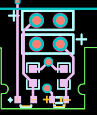 What are these connection points for? They are not mentioned in the schematics 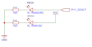 I need to connect to the positive pin of the Drive LED but it is a very small spot and close to the board edge and the Nunchuk. Not the most ideal place to solder a cable to. If I bridge the LED, will the port be able to handle the increased current? Any advice is appreciated. Best Regards Matthias |
||||
| Mixtel90 Guru Joined: 05/10/2019 Location: United KingdomPosts: 6781 |
I'm not sure of the CMM2, but I doubt if the LED signals are at 5V anyway, so not TTL level. They are more likely to be 3V3. I can't open the schematic at the moment to check. Have you considered making light pipe out of polycarbonate rod? I've done it a couple of times and it's very effective. Mick Zilog Inside! nascom.info for Nascom & Gemini Preliminary MMBasic docs & my PCB designs |
||||
| Page 1 of 3 |
|||||