|

|
Forum Index : Microcontroller and PC projects : PicoMite and MODBUS
| Author | Message | ||||
| Volhout Guru Joined: 05/03/2018 Location: NetherlandsPosts: 4223 |
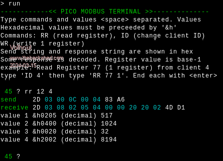
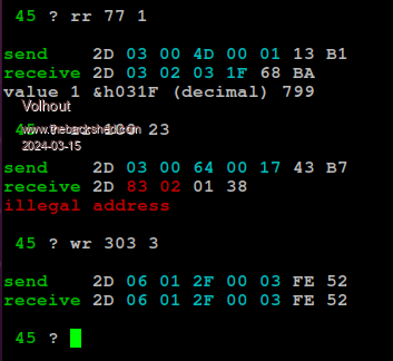
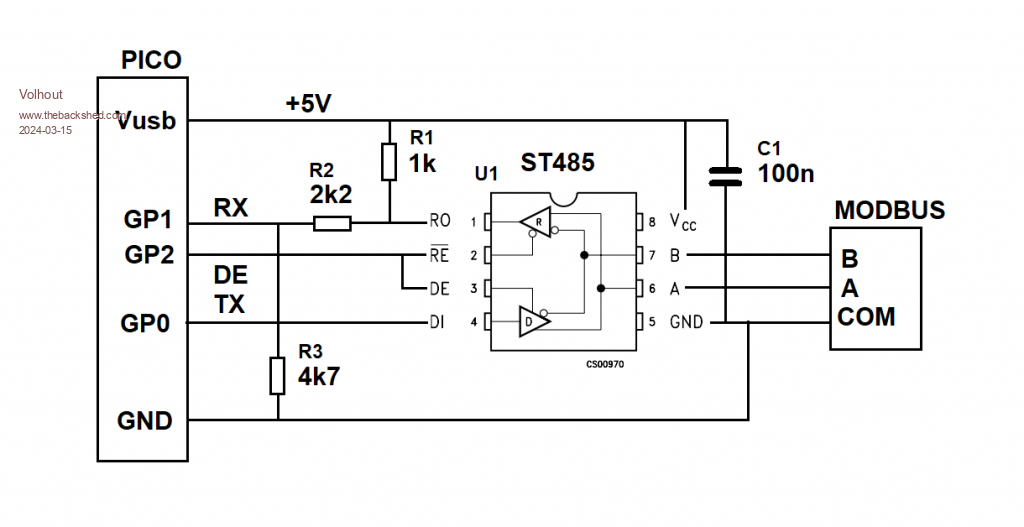
Hi All, This is by no means a complete project, it is a tool I needed for my job, and since the IT department is very restrictive on open source tools (read: cost = 0) installed on the companies computers, I hacked together a tool that uses a pico to connect to a modbus client. MODBUS TERMINAL The program uses a standard picomite (non-VGA, although it will run on a VGA) and should be controlled from a terminal program like PUTTY or TERATERM.  It uses ANSI colors to highlight the PDU (the payload).  I have implemented only the commands I need for this project. That is READ HOLDING REGISTER and WRITE SINGLE REGISTER but other commands can be added when needed. The hardware interface is this (I only had a 5V RS485 interface chip, if you have a 3.3V capable chip you can ommit R2 and R3). For long cables you want to add a 100 ohm resistor (termination) between A and B. But for my bench test this is fine.  The program is attached. I originally wanted to use interrupts for the receive side, but at higher baudrates this caused too many delays (since I control the DE pin from MMBasic). It is tested up to 115200 baud (default is 19200). I hope this is to someones use.... Volhout P.S. In my version, mor commands are implemented, but these reveal customer specific information, like the way to use a password to get into factory settings. These are removed from the version below. 'experiments for modbus RTU for commincation with VFD ' version can do ' 1 correct CRC calculation for modbus ' 2 send UART and control DE ' 3 assemble correct string for read register command ' 4 receives response from holding register read, no interrupt ' 5 pullup RX -> no BREAK, write 1 reg, help text, fault explain ' 6 t.b.d. option default integer option base 1 'ansi colors bl$=chr$(27)+"[36m" wh$=chr$(27)+"[37m" gr$=chr$(27)+"[32m" rd$=chr$(27)+"[31m" 'help strings rec$=gr$+"receive "+wh$ snd$=gr$+"send "+wh$ dim er$(4) length 16 = ("illegal function","illegal address","illegal value","slave fail") 'defaults for this modbus slave const bitrate=19200 'communication speed ID=45 'default modbus id 'init system openport 'serial port helptext 'show helptext on terminal 'repeated send string (old loop) do e$="" flush_rx parse pause 50 'just some time for a message to get in if loc(1) then e$=e$+input$(loc(1),#1) 'get answer 'e$=right$(e$,len(e$)-1) 'if needed strip break character during transmit print rec$;:prtx e$ decode e$ loop sub decode a$ local value,numbyte,i select case asc(mid$(a$,2,1)) case 03 'read numbyte=asc(mid$(a$,3,1)) for i=4 to 2+numbyte step 2 value=256*ASC(mid$(a$,i,1))+ASC(mid$(a$,i+1,1)) print "value";(i-2)/2;" &h";right$("000"+hex$(value),4);" (decimal)";value next case >127 'error print rd$;er$(asc(mid$(a$,3,1)));wh$ end select end sub 'this is the command loop, parsing text entered sub parse print : print gr$;ID;wh$;" "; : input txt$ : txt$=UCASE$(txt$) if left$(txt$,2)="ID" then ID=val(mid$(txt$,4)) 'robust if left$(txt$,2)="RR" then modsend mk_rd$(txt$) : print snd$;:prtx tx$ if left$(txt$,2)="WR" then modsend mk_wr$(txt$) : print snd$;:prtx tx$ end sub 'compiles the string for reading 16 bit holding register function mk_rd$(a$) local posi=4:hlp$=right$(a$,len(a$)-3) 'strip the function code 'register number and registeer range are 2 byte MSB first mk_rd$=chr$(ID)+chr$(3) 'ID + the modbus read register function 3 'get register number, and strip from string reg=val(hlp$):posi=instr(hlp$," "):if posi>1 then hlp$=right$(hlp$,len(hlp$)-posi) 'reg = reg - 1 'register start at 1 .... not used in documentation copeland mk_rd$=mk_rd$+chr$(reg\256)+chr$(reg and 255) 'get number of register to read num=val(hlp$) mk_rd$=mk_rd$+chr$(num\256)+chr$(num and 255) end function 'compiles the string for writing a single 16 bit register function mk_wr$(a$) local posi=4:hlp$=right$(a$,len(a$)-3) 'strip the function code 'register number and registeer range are 2 byte MSB first mk_wr$=chr$(ID)+chr$(6) 'ID + the modbus rwrite register function 6 'get register number, and strip from string reg=val(hlp$):posi=instr(hlp$," "):if posi>1 then hlp$=right$(hlp$,len(hlp$)-posi) 'reg = reg - 1 'register start at 1 .... not used in documentation copeland mk_wr$=mk_wr$+chr$(reg\256)+chr$(reg and 255) 'get the value to write to the register num=val(hlp$) mk_wr$=mk_wr$+chr$(num\256)+chr$(num and 255) end function 'prints the string send from UART in readable form on console sub prtx a$ local i for i=1 to len(a$) if i=2 then print choice(asc(mid$(a$,i,1))>127,rd$,bl$); if i=len(a$)-1 then print choice(check(a$),wh$,rd$); print right$("0"+hex$(asc(mid$(a$,i,1))),2);" "; next print wh$ end sub 'sends ID+PDU in string a$, adds CRC16 sub modsend a$ local m$=a$ 'calculate string crc and append crc to string crc_val=math(crc16 m$,len(m$),&h8005,&hffff,0,1 ,1) crcl=crc_val and 255:m$=m$+chr$(crcl) crch=crc_val \ 256:m$=m$+chr$(crch) 'calculate DE time ms_char!=11*1000/bitrate '1 char = 11 bits (start+8+parity+stop) ms_mess!=len(m$)*ms_char! 'message total time 'send it through the UART with controlled DE pin pin(gp2)=1 'DE high print #1,m$; pause ms_mess! pin(gp2)=0 'DE low tx$=m$ 'global string, just for debugging end sub 'opens the UART port for communication and the direction cotrol DE sub openport 'open COM1 port with modbus defaults 19200/8bit/even parity/1 stop setpin gp1, gp0, COM1 'rx,tx,port setpin gp2,dout : pin(gp2)=0 'DE pin is GP2 'open "COM1:"+str$(bitrate)+",256,have_data,EVEN" as #1 'interrupt driven open "COM1:"+str$(bitrate)+",EVEN" as #1 end sub 'checks if e received strin has matchin CRC in it function check(a$) local pd$,cr$ local crc_pd,crc_mes check=0 if len(a$)>3 then 'separate ID/PDU from message pd$=left$(a$,len(a$)-2) crc_pd=math(crc16 pd$,len(pd$),&h8005,&hffff,0,1 ,1) 'separate CRC from message cr$=right$(a$,2) crc_mes=256*asc(right$(cr$,1))+asc(left$(cr$,1)) 'compare CRC's -> when equal, message is okay. if crc_mes=crc_pd then check=1 end if end function 'flush the USRT rx buffer sub flush_rx local dum$ 'print loc(1) if loc(1) then dum$=input$(loc(1),#1) end sub sub helptext print gr$+"------------<< PICO MODBUS TERMINAL >>--------------" print "Type commands and values <space> separated. Values " print "Hexadecimal values must be preceeded by '&h'" print "Commands: RR (read register), ID (change client ID) " print "WR (write 1 register) print "Send string and response string are shown in hex" print "Some response is decoded. Register value is base-1" print "example: Read Register 77 (1 register) from client 4" print "type 'ID 4' then type 'RR 77 1'. End each with <enter>" end sub Edited 2024-03-15 22:45 by Volhout PicomiteVGA PETSCII ROBOTS |
||||
| Ossi Newbie Joined: 22/06/2023 Location: GermanyPosts: 6 |
Hi Volhout, This is great work. I had already tried to read the data from my solar inverter to control my loads in the house. My automation runs on atmega32 and is written in assembler, so I had problems with the CRC calculation. So far I only listen the traffic between the inverter and the power meter to get a few values. Reading many more values in the future with a PicoW directly from the inverter is a cheap and elegant solution. Thanks for the publication. Ossi |
||||
| Volhout Guru Joined: 05/03/2018 Location: NetherlandsPosts: 4223 |
Dear Ossi, I am glad it works for you. Volhout PicomiteVGA PETSCII ROBOTS |
||||
| Volhout Guru Joined: 05/03/2018 Location: NetherlandsPosts: 4223 |
This is an updated version of the MODBUS RTU terminal. - When PicoMiteVGA then the VGA screen is used as terminal - When PicoMite then Teraterm/Putty is treated as the terminal - Implemented write to multiple registers (WM) and write of a string to a single register (WS). This is the code. 'experiments for modbus RTU for commincation with VFD ' version can do ' 1 correct CRC calculation for modbus ' 2 send UART and control DE ' 3 assemble correct string for read register command ' 4 receives response from holding register read, no interrupt ' 5 pullup RX -> no BREAK, write 1 reg, help text, fault explain ' 6 write multiple ' 7 write string according Customer procedure (modbus ??) werkt ' WS reg DIT_IS_DE_TEXT format. ' 8 VGA color option default integer option base 1 'check if main output is VGA screen or console vga=(mm.device$="PicoMiteVGA") 'ansi colors bl$=chr$(27)+"[36m" wh$=chr$(27)+"[37m" gr$=chr$(27)+"[32m" rd$=chr$(27)+"[31m" 'help strings rec$="receive " snd$="send " dim er$(4) length 16 = ("illegal function","illegal address","illegal value","slave fail") 'defaults for customer VFD const bitrate=19200 'communication speed ID=45 'default modbus id 'init system openport 'serial port cls helptext 'show helptext on terminal 'repeated send string (old loop) do e$="" flush_rx parse pause 50 'just some time for a message to get in if loc(1) then e$=e$+input$(loc(1),#1) 'get answer 'e$=right$(e$,len(e$)-1) 'if needed strip break character during transmit if vga then color rgb(green):print rec$;:color rgb(white) else print gr$;rec$;wh$; end if prtx e$ decode e$ loop sub decode a$ local value,numbyte,i select case asc(mid$(a$,2,1)) case 03 'read numbyte=asc(mid$(a$,3,1)) for i=4 to 2+numbyte step 2 value=256*ASC(mid$(a$,i,1))+ASC(mid$(a$,i+1,1)) print " reg";reg-1+(i-2)/2;" = &h";right$("000"+hex$(value),4);" (decimal)";value next case >127 'error if vga then color rgb(red):print er$(asc(mid$(a$,3,1))):color rgb(white) else print rd$;er$(asc(mid$(a$,3,1)));wh$ end if end select end sub 'this is the command loop, parsing text entered sub parse if vga then color rgb(green):print ID;" ";:color rgb(white) else print gr$;ID;" ";wh$; end if input txt$ : txt$=UCASE$(txt$) select case left$(txt$,2) case "RR" modsend mk_rd$(txt$) case "WR" modsend mk_wr$(txt$) case "WM" modsend mk_wm$(txt$) case "WS" modsend mk_ws$(txt$) end select if left$(txt$,2)="ID" then ID=val(mid$(txt$,4)) else if vga then color rgb(green):print snd$;:color rgb(white) else print gr$;snd$;wh$ end if prtx tx$ end if end sub 'compiles the string for reading 16 bit holding register function mk_rd$(a$) local posi=4:hlp$=right$(a$,len(a$)-3) 'strip the function code 'register number and registeer range are 2 byte MSB first mk_rd$=chr$(ID)+chr$(3) 'ID + the modbus read register function 3 'get register number, and strip from string reg=val(hlp$):posi=instr(hlp$," "):if posi>1 then hlp$=right$(hlp$,len(hlp$)-posi) 'reg = reg - 1 'register start at 1 .... not used in documentation mk_rd$=mk_rd$+chr$(reg\256)+chr$(reg and 255) 'get number of register to read num=val(hlp$) mk_rd$=mk_rd$+chr$(num\256)+chr$(num and 255) end function 'compiles the string for writing a single 16 bit register function mk_wr$(a$) local posi=4:hlp$=right$(a$,len(a$)-3) 'strip the function code 'register number and registeer range are 2 byte MSB first mk_wr$=chr$(ID)+chr$(6) 'ID + the modbus write register function 6 'get register number, and strip from string reg=val(hlp$):posi=instr(hlp$," "):if posi>1 then hlp$=right$(hlp$,len(hlp$)-posi) 'reg = reg - 1 'register start at 1 .... not used in documentation mk_wr$=mk_wr$+chr$(reg\256)+chr$(reg and 255) 'get the value to write to the register num=val(hlp$) mk_wr$=mk_wr$+chr$(num\256)+chr$(num and 255) end function 'compiles the string for writing multiple 16 bit registers function mk_wm$(a$) local posi=4:hlp$=right$(a$,len(a$)-3) 'strip the function code 'register number and registeer range are 2 byte MSB first mk_wm$=chr$(ID)+chr$(16) 'ID + the modbus rwrite register function 6 'get register number, and strip from string reg=val(hlp$):posi=instr(hlp$," "):if posi>1 then hlp$=right$(hlp$,len(hlp$)-posi) 'reg = reg - 1 'register start at 1 .... not used in documentation mk_wm$=mk_wm$+chr$(reg\256)+chr$(reg and 255) 'get register count, and strip from string num=val(hlp$):posi=instr(hlp$," "):if posi>1 then hlp$=right$(hlp$,len(hlp$)-posi) mk_wm$=mk_wm$+chr$(num\256)+chr$(num and 255)+chr$(num*2 and 255) 'values(16b)+bytes 'num is number of 16 bit values to follow for i=1 to num 'get the value to write to the register dat=val(hlp$):posi=instr(hlp$," "):if posi>1 then hlp$=right$(hlp$,len(hlp$)-posi) mk_wm$=mk_wm$+chr$(dat\256)+chr$(dat and 255) next end function 'compiles the string for writing text in one registers function mk_ws$(a$) local posi=4:hlp$=right$(a$,len(a$)-3) 'strip the function code 'register number and registeer range are 2 byte MSB first mk_ws$=chr$(ID)+chr$(06) 'ID + the modbus write single register function 6 'get register number, and strip from string reg=val(hlp$):posi=instr(hlp$," "):if posi>1 then hlp$=right$(hlp$,len(hlp$)-posi) 'reg = reg - 1 'register start at 1 .... not used in documentation mk_ws$=mk_ws$+chr$(reg\256)+chr$(reg and 255) 'rest of the command string is text, append it 'I am not sure this is MODBUS compliant, but customer uses it this way mk_ws$=mk_ws$+hlp$ end function 'prints the string send from UART in readable form on console sub prtx a$ local i for i=1 to len(a$) if i=2 then if vga then color choice(asc(mid$(a$,i,1))>127,rgb(red),rgb(cyan)) else print choice(asc(mid$(a$,i,1))>127,rd$,bl$); end if end if if i=len(a$)-1 then if vga then color choice(check(a$),rgb(white),rgb(red)) else print choice(check(a$),wh$,rd$); end if end if print right$("0"+hex$(asc(mid$(a$,i,1))),2);" "; next if vga then print :color rgb(white) else print wh$ end if end sub 'sends ID+PDU in string a$, adds CRC16 sub modsend a$ local m$=a$ 'calculate string crc and append crc to string crc_val=math(crc16 m$,len(m$),&h8005,&hffff,0,1 ,1) crcl=crc_val and 255:m$=m$+chr$(crcl) crch=crc_val \ 256:m$=m$+chr$(crch) 'calculate DE time ms_char!=11*1000/bitrate '1 char = 11 bits (start+8+parity+stop) ms_mess!=len(m$)*ms_char! 'message total time 'print ms_mess! 'debug 'send it through the UART with controlled DE pin pin(gp2)=1 'DE high print #1,m$; pause ms_mess! pin(gp2)=0 'DE low tx$=m$ 'global string, just for debugging end sub 'opens the UART port for communication and the direction cotrol DE sub openport 'open COM1 port with modbus defaults 19200/8bit/even parity/1 stop setpin gp1, gp0, COM1 'rx,tx,port setpin gp2,dout : pin(gp2)=0 'DE pin is GP2 open "COM1:"+str$(bitrate)+",EVEN" as #1 end sub 'checks if e received strin has matchin CRC in it function check(a$) local pd$,cr$ local crc_pd,crc_mes check=0 if len(a$)>3 then 'separate ID/PDU from message pd$=left$(a$,len(a$)-2) crc_pd=math(crc16 pd$,len(pd$),&h8005,&hffff,0,1 ,1) 'separate CRC from message cr$=right$(a$,2) crc_mes=256*asc(right$(cr$,1))+asc(left$(cr$,1)) 'compare CRC's -> when equal, message is okay. if crc_mes=crc_pd then check=1 end if end function 'flush the USRT rx buffer sub flush_rx local dum$ 'print loc(1) if loc(1) then dum$=input$(loc(1),#1) end sub sub helptext if vga then color rgb(green) else print gr$; Print "-----------<< PICO MODBUS RTU TERMINAL >>-------------" if vga then color rgb(white) else print wh$; Print "Type commands and values <space> separated values." Print "Hexadecimal values must preceeded '&h'. Commands :" Print "ID (change client ID) = ID xx " Print "RR (read registers) = RR reg num" Print "WR (write 1 register) = WR reg val" Print "WM (write multi registers)= WM reg num val1 val2 .." Print "WS (write text string) = WS reg TEXT_STRING" Print "Send string and response string are shown in hex" Print "Some response is decoded. Register value is base-1" Print "example: Read Register 77 (1 register) from client 4" Print "type 'ID 4' then type 'RR 77 1'. End each with <enter>" end sub PicomiteVGA PETSCII ROBOTS |
||||
| Volhout Guru Joined: 05/03/2018 Location: NetherlandsPosts: 4223 |
New release with minor changes. Up to now I used a PicoMiteVGA for the job. For field work, I created a adaptor cable for the laptop, using a RP2040-ZERO and a RS485 interface chip. Use TeraTerm or Putty, since these support the ANSI colors in the terminal window. The WS2812 LED on the zero shows status GREEN = OK CYAN = waiting for answer (no response) RED = MODBUS failure Code: modbus12.zip Photo of actual interface before sleeving: Volhout Edited 2024-07-03 19:39 by Volhout PicomiteVGA PETSCII ROBOTS |
||||
| Mixtel90 Guru Joined: 05/10/2019 Location: United KingdomPosts: 6783 |
That's very neat. :) Mick Zilog Inside! nascom.info for Nascom & Gemini Preliminary MMBasic docs & my PCB designs |
||||
| Volhout Guru Joined: 05/03/2018 Location: NetherlandsPosts: 4223 |
Mick, others, Implemented timeout and retries. Normally these would not be needed for manual interaction, but I needed it for some of the recent clients. Defines of timeout and retries are in the MMBasic program. Modify at will. 'modbus defines looptime=50 'ms timeout=1000 'ms loops=timeout/looptime 'number of loops in 1000ms retries=5 'number of retries modbus13.zip Volhout Edited 2024-07-03 20:52 by Volhout PicomiteVGA PETSCII ROBOTS |
||||