|

|
Forum Index : Microcontroller and PC projects : A new Pico PCB for V5.09.00 - comments
| Page 1 of 3 |
|||||
| Author | Message | ||||
| matherp Guru Joined: 11/12/2012 Location: United KingdomPosts: 9115 |
Existing PCB designs for LCDs all suffer from the slow speed of transfer to the screen so I thought can I get the Pico to support a full 16-bit parallel RGB565 I/F and still make it useful? The answer was NO However, I could get it to support RGB555 and that one pin makes the difference. With the new USB support for Keyboard, mouse and game controllers the allocation of every single pin on the RP2040 is not the issue it would have been previously. Here is the design: 3e2a4967-01dd-411f-8f0d-87a8da272427.pdf The intention is that this design can, if you wish, be used completely standalone with the LCD acting as the console device and, of course, a USB keyboard for input. Pins GP0 to GP15 are the data pins for the LCD except that GP5 (least significant bit of green) is not connected and G0 on the LCD is connected to G1 GP16, GP17, and GP18 are the control lines for the LCD. The reset line is connected to the processor reset which in turn is controlled by a proper reset controller chip (TCM809) GP5 and GP19 are used for the touch I/O (CS and IRQ) GP20, GP22 and GP23 are SYSTEM SPI GP21 is the SDcard chip select GP24 and GP25 are the SYSTEM I2C and control the RTC and a pair of 8-bit port expanders (TCA6408) that individually can be selected for 3.3 or 5V I/O and connect to a 20-pin card-edge header GP26 and GP27 are the audio output pins and output via a line level jack and stereo PAM8302 amplifiers and finally GP28 and GP29 are the serial console connected to the outside world by a ch340 USB to TTL convertor. The USB-C connector for the serial console also provides the power. I've included interfaces for both 34-pin and 40-pin LCDs so that covers: 2 variants of ILI9341 All variants of SSD1963 up to 7" (480x272 and 800x480) and both types of 4" 800x480 LCD (OTM8009A and NT35510) The reason for pairs of both the 34-pin and 40-pin headers is to allow screens of different sizes to be roughly centered, however 1 or both of the duplicates may not survive the layout phase. Thoughts? |
||||
| thwill Guru Joined: 16/09/2019 Location: United KingdomPosts: 4038 |
You need to get a hobby  . .Hope you are having a good weekend, Tom Game*Mite, CMM2 Welcome Tape, Creaky old text adventures |
||||
| Amnesie Guru Joined: 30/06/2020 Location: GermanyPosts: 396 |
Nice, but the "old" PicoMiteVGA firmware with PS/2 is still supported? For me I don't see the need for USB and it would be bad if I now have to abandon all my picoMiteVGA PCB designs. -Daniel |
||||
| Mixtel90 Guru Joined: 05/10/2019 Location: United KingdomPosts: 6786 |
This is an alternative to the VGA - it's a much-upgraded standard PicoMite. The display will be fast as it's 16-bit parallel - good for the larger screen LCDs. It will also make good use of colour on those displays (you get more colour on LCD than you can get on the PicoMite VGA). So, it's different to the PicoMite VGA, not a replacement for it. Comment for Peter: The thing that would bother me most would be the choice of the TCA6408. This appears to be SMD only, but all the data pins are exposed on the GPIO connector. Any damage to a pin is a SMD replacement rather than simply swapping a DIL like a MCP23008 or something similar. Alternatively a Pico could be used as a GPIO output (it's a bit big though). Edited 2024-02-11 05:25 by Mixtel90 Mick Zilog Inside! nascom.info for Nascom & Gemini Preliminary MMBasic docs & my PCB designs |
||||
| matherp Guru Joined: 11/12/2012 Location: United KingdomPosts: 9115 |
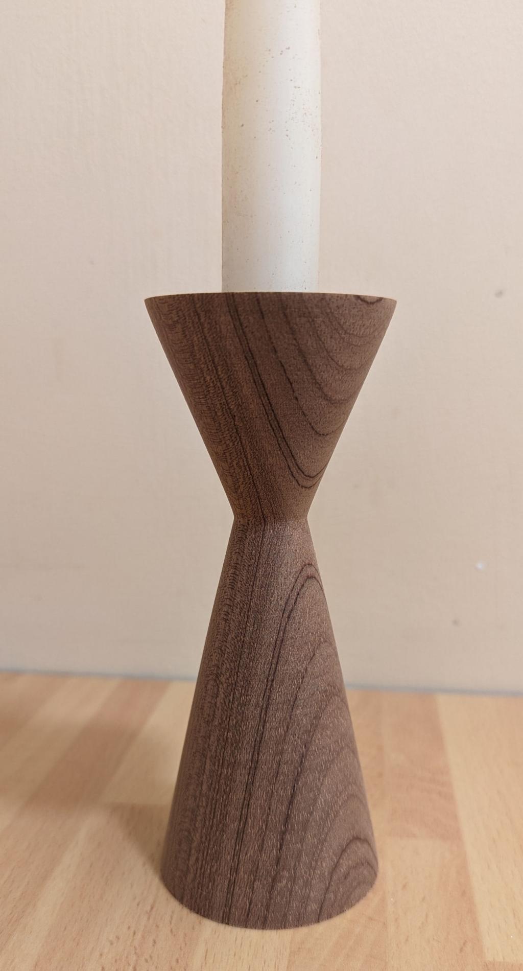
Yes, of course. If you download the 5.09.00 beta you will see there are now 3 variants. Got lots. Turned this earlier today (new old lathe arrived yesterday)  |
||||
| thwill Guru Joined: 16/09/2019 Location: United KingdomPosts: 4038 |
I'm very jealous. Tom Game*Mite, CMM2 Welcome Tape, Creaky old text adventures |
||||
| stanleyella Guru Joined: 25/06/2022 Location: United KingdomPosts: 2127 |
Interesting ideas. would i2c to parallel display be same speed as to i2c display? a dual dil port expander also and no stereo amp, power from usb |
||||
| Mixtel90 Guru Joined: 05/10/2019 Location: United KingdomPosts: 6786 |
A graphic LCD RGB555 display over I2C would be painfully slow. It's not practical because there's a lot of data to transfer. What matherp is proposing is probably the fastest RGB555 display you can get on a PicoMite. The price you pay is the number of GPIO pins used, hence the port expanders to get some back. Mick Zilog Inside! nascom.info for Nascom & Gemini Preliminary MMBasic docs & my PCB designs |
||||
| stanleyella Guru Joined: 25/06/2022 Location: United KingdomPosts: 2127 |
I see. |
||||
| Volhout Guru Joined: 05/03/2018 Location: NetherlandsPosts: 4233 |
Hi Peter, By connecting G0 to G1 on the LCD, can you still configure the LCD driver correctly ? I assume the data lines are also used for configuration. Can you still do hardware scrolling on the SSD display ? Regards, Volhout Edited 2024-02-11 21:02 by Volhout PicomiteVGA PETSCII ROBOTS |
||||
| matherp Guru Joined: 11/12/2012 Location: United KingdomPosts: 9115 |
No, I realised this last night too - I'm going to have to try and multiplex the use of one of the pins or something. This problem only arises with the need for a serial console on the USB version. The standard PicoMite has enough pins assuming all I/O is through the port expanders. Yes Edited 2024-02-12 00:41 by matherp |
||||
| stanleyella Guru Joined: 25/06/2022 Location: United KingdomPosts: 2127 |
When I used ili9341 with a uno and great cow basic, I didn't connect lcd reset to uno, I tied it high. Scoped picomite ili9341 reset and seems hi always. any use? |
||||
| matherp Guru Joined: 11/12/2012 Location: United KingdomPosts: 9115 |
I've now got most of the 16-bit drivers working except for the IPS 800x480 displays Here are some timings for interest on a ILI9341 in different modes - all in mSec SPI 8-BIT 16-BIT CLS 35.0 27.2 6.6 FRAMEBUFFER COPY 35.3 23.2 9.7 FRAMEBUFFER MERGE 47.8 26.1 12.7 |
||||
| karlelch Senior Member Joined: 30/10/2014 Location: GermanyPosts: 172 |
Interesting. Why is 16bit so much faster? |
||||
| darthvader Regular Member Joined: 31/01/2020 Location: FrancePosts: 76 |
Because in SPI you send bit per bit (so as serial and i2c) , in 8 bits you send 2 bytes and in 16 bits you just send one word  , it's allot faster but take allot more pins , it's allot faster but take allot more pins  @Peter : What was the mcu speed for this results ? , i tested some years ago on stm32h7 at 480 Mhz with DMA2D and LDTC at something like 1.2 to 1.4mS for CLS and your result are impressive with no dedicated hardware  Theory is when we know everything but nothing work ... Practice is when everything work but no one know why ;) |
||||
bigmik Guru Joined: 20/06/2011 Location: AustraliaPosts: 2914 |
Hi Peter, All, Do you think that by using a pair of fast 8 bit latches (1 high order the other low order) and 9 GPIO you could still get the required 16 pins, albeit with 2 x 8 bit loads using the 9th bit to control which latch is read to. Then both latches (together) provide the 16 required bits. This will no doubt be slower than direct 16 bits but still should be considerably faster than a single SPI. The sequence could be like, enable high order latch, write relevant 8 bits, enable low order latch write relevant 8 bits, enable TFT, clock in the latched 16bits. Yes requires extra latch circuitry but I think is a possibility. Just tossing it out there for consideration. Kind Regards, Mick Mick's uMite Stuff can be found >>> HERE (Kindly hosted by Dontronics) <<< |
||||
| Mixtel90 Guru Joined: 05/10/2019 Location: United KingdomPosts: 6786 |
Some of the displays can be set for either 8-bit or 16-bit operation. I'm thinking of the parallel version of the ILI9341 in particular. Mick Zilog Inside! nascom.info for Nascom & Gemini Preliminary MMBasic docs & my PCB designs |
||||
| Volhout Guru Joined: 05/03/2018 Location: NetherlandsPosts: 4233 |
@Peter, Assuming you do not want to use the 6'th bit of green (G0) for video data, but do want the bit diring setup, you could use the LCD display D line (distinguishes between register write and scrren write) to switch a 74LV1G18 (single gate mux) on the GP5 pin. Then the pin is used for Touch CS when you are writing to screen, and touch is disconnected when setting up the LCD driver IC. The 74LVC1G18 chip is a SOT23-6, and is easier to solder than the RP2040, much easier. You have to use pullup(CS)/pulldown(G0) resistors for the outputs, just to make sure they are in controlled state when not used. Volhout Edited 2024-02-12 17:25 by Volhout PicomiteVGA PETSCII ROBOTS |
||||
| matherp Guru Joined: 11/12/2012 Location: United KingdomPosts: 9115 |
I've been thinking more about this and the best solution I can come up with is combining TOUCH_CS and SD_CS on a single pin with an inverting transistor to one of chip selects. By definition, since they share the same SPI bus, only one can be low at any one time. With a bit of thought it should be possible to also allow both to be high by putting the output in high-Z mode. If any of the electronics wizards want to propose a simple circuit to get all three states from a single pin I would be very appreciative The truth table I want is Input Output 1 Output 2 HighZ H H low L H high H L Edited 2024-02-14 05:40 by matherp |
||||
| Mixtel90 Guru Joined: 05/10/2019 Location: United KingdomPosts: 6786 |
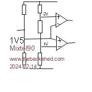
I was looking at your circuit earlier today, wondering if there was a way to use it with the YD-RP2040. I hope it's me that's messed up, but is it correct that GP6 is going to two adjacent data pins on the display? I can get your truth table with a twin op-amp (or comparator) and 5 resistors... bias the pico output to 1.fv use a string of 3 resistors to get 1V and 2V points for the op amp inputs. it's like a 555. - on the top is linked to + on the bottom is linked to the pico output. Now the top op amp goes low if the pico is high and the bottom op amp ios low if the pico is low.  Edited 2024-02-14 06:01 by Mixtel90 Mick Zilog Inside! nascom.info for Nascom & Gemini Preliminary MMBasic docs & my PCB designs |
||||
| Page 1 of 3 |
|||||