|

|
Forum Index : Microcontroller and PC projects : Sweetie-Pi-coMite VGA. Sorry, couldn't resist!
| Page 1 of 2 |
|||||
| Author | Message | ||||
| Mixtel90 Guru Joined: 05/10/2019 Location: United KingdomPosts: 6786 |
*UNTESTED* - HERE BE DRAGONS! This uses Peter's facility to move the VGA pins to good advantage. It allows VGA output from a RP2040-Zero for the first time. I wonder if, as the PCB is only 50mm square, this might be a contender for the smallest fully user programmable games console? :) Sorry, no RTC on this one (not enough space), but it has got an expansion port. GP28 (on the above) is, by default, used to detect a WII controller. If GP28 is high then a controller is plugged in and is the correct way up. There should be no damage if the controller is plugged in upside down as the supply is disconnected with this design. GP28 can be isolated from the WII connector via a solder blob link. It *should* work with: OPTION PICO OFF '(we need GP29) OPTION SYSTEM I2C GP2, GP3 OPTION SDCARD GP29, GP1, GP4, GP0 OPTION AUDIO SPI GP5, GP6, GP7 OPTION VGA PINS GP14, GP10 Note! The RP2040-Zero does not isolate the USB input via a diode. It might be a bad idea to power the board from the barrel jack while the USB is plugged in. There isn't as much need for a barrel jack when you have USB-C though. Mick Zilog Inside! nascom.info for Nascom & Gemini Preliminary MMBasic docs & my PCB designs |
||||
| lizby Guru Joined: 17/05/2016 Location: United StatesPosts: 3150 |
Love it--so compact. 50mm--does that mean it can be panelized 4 to a PCB? What a great instructional tool this would be for a teacher who wasn't afraid to have pupils soldering (or for an after-class club). Tiny--but with MMBasic, incredibly powerful. If panelizable, 20 PCBs for under $5. PicoMite, Armmite F4, SensorKits, MMBasic Hardware, Games, etc. on fruitoftheshed |
||||
| Mixtel90 Guru Joined: 05/10/2019 Location: United KingdomPosts: 6786 |
You could only get two out of a 100x100 board because you have to allow for some waste edges for the machine to grip. Because of the cutting out for the WII socket it might make panelization rather more expensive than buying individual boards, although using two to a panel and putting the WII sockets opposite to each other on the non-grip edges would be fine. If you were going to use it as an educational device then it might be better to get the microSD hard holder pre-mounted at least. They are fiddly to solder. Incidentally, I use that type because it will fit! Mick Zilog Inside! nascom.info for Nascom & Gemini Preliminary MMBasic docs & my PCB designs |
||||
| lizby Guru Joined: 17/05/2016 Location: United StatesPosts: 3150 |
My preference is certainly for the 6-pin micro SD module--far easier to solder, and 5 cost less than one of the sockets on this board (at Digikey). But space is at a premium. PicoMite, Armmite F4, SensorKits, MMBasic Hardware, Games, etc. on fruitoftheshed |
||||
| Mixtel90 Guru Joined: 05/10/2019 Location: United KingdomPosts: 6786 |
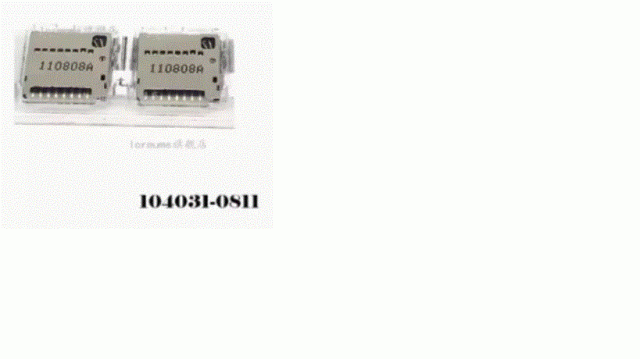
The 104031-0811 sockets are currently £3.38 + postage & VAT for 10 from AE. Not very expensive, just a little fiddly. I bought 20 a while ago as I decided to try to minimize dependency on ready built modules. Mick Zilog Inside! nascom.info for Nascom & Gemini Preliminary MMBasic docs & my PCB designs |
||||
| lizby Guru Joined: 17/05/2016 Location: United StatesPosts: 3150 |
Can you provide a link? I've bought 2 sets which are wrong. The ones I'm finding now have a width of 14+mm, whereas the ones with that part number on Digikey appear to be 11.8mm. PicoMite, Armmite F4, SensorKits, MMBasic Hardware, Games, etc. on fruitoftheshed |
||||
| Mixtel90 Guru Joined: 05/10/2019 Location: United KingdomPosts: 6786 |
see if this works. The number printed on each socket is 131117A and the bag they came in is labelled 10431 0811. They are 12mm wide. They look like the ones in the official drawing on Mouser's site, right down to the hole punching. They say they are 11.95mm wide, but my ruler isn't that accurate. :) Edited 2024-01-22 03:37 by Mixtel90 Mick Zilog Inside! nascom.info for Nascom & Gemini Preliminary MMBasic docs & my PCB designs |
||||
Grogster Admin Group Joined: 31/12/2012 Location: New ZealandPosts: 9306 |
You're getting pretty good at Sprint Layout now!  I must admit to using the WS Zero module more and more. Initially, this was because during the worst of the virus, the global silicon-chip shortage forced me to redesign to use the 2040 chip - simply because it was plentiful at the time, and Peter had wonderfully ported MMBASIC to it. But I find it more and more useful, as it has it's own on-board 3v3 regulator I can tap into, and cos you program it directly via its USB-C connector, the 1455 USB chip can be dropped from the host PCB layout among other things, so you end up with a smaller component count then using the PIC32 original chip(normally the 170 MM2 in SOIC or SSOP for me). I have had no stability issues with the current Pico firmware on the WS Zero module, so I have just started using them more and more - the entire module is about the same price as one PIC32 chip, so in these days of having to tighten our financial belts a bit more post-virus economy, that works well too. Smoke makes things work. When the smoke gets out, it stops! |
||||
| lizby Guru Joined: 17/05/2016 Location: United StatesPosts: 3150 |
Thanks. I did not see any imprinted with 131117A, but I ordered this one  PicoMite, Armmite F4, SensorKits, MMBasic Hardware, Games, etc. on fruitoftheshed |
||||
| Mixtel90 Guru Joined: 05/10/2019 Location: United KingdomPosts: 6786 |
They look like they might be the ones. They are all made in China anyway. :) Yep, I like the 'Zero. It seems to be rock solid running MMBasic. You get less GPx pins, but that's the point - you don't have them going to waste. :) Having a Reset button and WS2812B LED are nice icing on the cake. There are a couple of minor disadvantages though, RUN and 3V3EN aren't available on pins. The latter is useful because it can be used as an on/off switch. The regulator has the necessary enable input too. Of course, breadboard compatibility has had to go but you can develop on a standerd Pico and transfer stuff over. I realized - if you arrange these boards on a 100x100 with the WII connectors outwards you can get 4 to a board providing you cut them up yourself. Having the VGA & PS2 connectors to the middle allows for the width of the cutting blade as this dimension is non-critical (at least to a mm or two). If you want JLC to panelize them then you will need a longer board and the price will go up. They now charge for panelizing anyway I think. Mick Zilog Inside! nascom.info for Nascom & Gemini Preliminary MMBasic docs & my PCB designs |
||||
| Volhout Guru Joined: 05/03/2018 Location: NetherlandsPosts: 4228 |
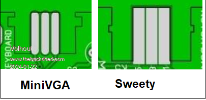
Hi Mick, I have build few of your VGA board with the board edge WII connector, and before you release this one you may be able to "tune" the board edge connector a bit. 1/ the cutouts for the locks can be smaller and the edge facing outward can be 0.5mm more inward (when locked, the connector can still be pushed 1mm more inward). Tested this with a nunchuck and my (finally arrived) classic controller. 2/ the locks just "barely" lock. It is absolutely possible to push in the connector at 15 degrees, where only 1 lock locks. Maybe the edges that have the lock cutouts can be brought closer together to force the connector alignment. I am not sure how much of this is due to JLC tollerances. Maybe you could check your board dimensions with the WII connectors (I assume you received these already). Volhout PicomiteVGA PETSCII ROBOTS |
||||
| Mixtel90 Guru Joined: 05/10/2019 Location: United KingdomPosts: 6786 |
Thanks for the info. I'll have another look at the connector. I didn't have any official connectors when I drew the SL6 macro. TBH I hate that arrangement and I'd much rather use anything else with the necessary four pins. Even Duponts. The locking system is excellent when used with the matching PCB connector, but unfortunately it's a struggle to get those. I'm doubtful if they are even being manufactured now - we may be seeing old stock as they only appear to be used as spares for WII controllers. The last of those was made over 10 years ago! I'm currently intending to use the official connectors on PicoGAME 4 but only because I'll get moaned at if I expect people to make adapters or change the lead for one with a RJ12 6P4C on it. Mick Zilog Inside! nascom.info for Nascom & Gemini Preliminary MMBasic docs & my PCB designs |
||||
| Volhout Guru Joined: 05/03/2018 Location: NetherlandsPosts: 4228 |
Maybe you already did ....???  Volhout PicomiteVGA PETSCII ROBOTS |
||||
| Mixtel90 Guru Joined: 05/10/2019 Location: United KingdomPosts: 6786 |
Ah... perhaps I did... Memory has never been my strong point. :) I'll check anyway. Mick Zilog Inside! nascom.info for Nascom & Gemini Preliminary MMBasic docs & my PCB designs |
||||
| lizby Guru Joined: 17/05/2016 Location: United StatesPosts: 3150 |
Can you set V-grooves without JLC charging you for the panelization? PicoMite, Armmite F4, SensorKits, MMBasic Hardware, Games, etc. on fruitoftheshed |
||||
| Mixtel90 Guru Joined: 05/10/2019 Location: United KingdomPosts: 6786 |
Not as far as I know. There's no way to do it in SL6. You could probably drill a row of little holes on the dividing line, but it wouldn't be a V groove. How it would be charged I don't know. If you just use silkscreen lines it's a simple cost, but they may charge for extra machining if it's obvious that the board can be split up. You have to weigh up the costs when a table saw & blades is in the region of £40, which would pay for itself over a few boards. Mick Zilog Inside! nascom.info for Nascom & Gemini Preliminary MMBasic docs & my PCB designs |
||||
Grogster Admin Group Joined: 31/12/2012 Location: New ZealandPosts: 9306 |
I've done V-grooves before in the past - just use the outline layer to draw lines around your boards, where you want the V-grooves to be. JLC did not used to charge extra for V-grooving, but as Mick says, I think they do now. Even if the panel consists of all the same design. Smoke makes things work. When the smoke gets out, it stops! |
||||
| Mixtel90 Guru Joined: 05/10/2019 Location: United KingdomPosts: 6786 |
I've re-done the WII connector to a tighter tolerance after measuring the proper things. I'm doing a circuit diagram too. JLCPCB appear to do 4 to a 100x100mm board, separated by screen printed lines only, for their usual $2 special price. If I've understood it right, it's $7.80 if you want them V grooved. I'm not certain that I've got it right though. :) Mick Zilog Inside! nascom.info for Nascom & Gemini Preliminary MMBasic docs & my PCB designs |
||||
| lizby Guru Joined: 17/05/2016 Location: United StatesPosts: 3150 |
Got gerbers yet ready for release, or still tinkering? PicoMite, Armmite F4, SensorKits, MMBasic Hardware, Games, etc. on fruitoftheshed |
||||
| Mixtel90 Guru Joined: 05/10/2019 Location: United KingdomPosts: 6786 |
Only slight tinkering. They'll be ready very soon. :) Mick Zilog Inside! nascom.info for Nascom & Gemini Preliminary MMBasic docs & my PCB designs |
||||
| Page 1 of 2 |
|||||