|

|
Forum Index : Microcontroller and PC projects : Layer Stack for Maximite Gen 2
| Author | Message | ||||
| CtrlAltSockPuppet Newbie Joined: 05/01/2024 Location: United KingdomPosts: 11 |
Hi I am currently looking into the feasibility of having a PCB fabricated for a Gen 2 Maximite. I was told that, there is no layer stack, within the project and I was asked if ground was layer 2. Can anyone help please? Thank you Jeff |
||||
| matherp Guru Joined: 11/12/2012 Location: United KingdomPosts: 9115 |
Top Copper Layer 2 is GND 3V3 Bottom Copper |
||||
| CtrlAltSockPuppet Newbie Joined: 05/01/2024 Location: United KingdomPosts: 11 |
Thank you very much |
||||
| matherp Guru Joined: 11/12/2012 Location: United KingdomPosts: 9115 |
It wouldn't really matter if the GND and 3.3V layers were swapped but it is probably better to have the GND as close as possible to the CPU and memory. Where it would matter is in a PCB with blind vias but those add a huge chunk to the price so I've never used them. |
||||
| CtrlAltSockPuppet Newbie Joined: 05/01/2024 Location: United KingdomPosts: 11 |
That's handy to bear in mind. I noticed that when I uploaded the component placement file to the PCB manufacturer, all the components with a polarisation, were interpreted by the vendors software to have incorrect orientations. Such as the microcontroller and the polarised capacitors etc. They include buttons, to rotate components, so I assume it's a common issue. |
||||
| matherp Guru Joined: 11/12/2012 Location: United KingdomPosts: 9115 |
When I originally did them I had to change the orientations in the placement file because they were showing wrong. Sounds like they may have corrected at their end so my fixes are no longer needed. I assume you used my xls files? |
||||
| CtrlAltSockPuppet Newbie Joined: 05/01/2024 Location: United KingdomPosts: 11 |
Yes, I used the XLS files from here: https://geoffg.net/Downloads/Maximite/CMM2_Construction_Pack.zip |
||||
| CtrlAltSockPuppet Newbie Joined: 05/01/2024 Location: United KingdomPosts: 11 |
I'd like to say a big thank you, to you Peter and Geoff for creating the Maximite and so generously sharing it. I became a self-taught engineer in the 1980's off the back of the home computers of the time. I've not worked in that field for 30+ years. But your Maximite design, (echoing the home computers from the 80's), has inspired me to clean off the rust from my skills and get involved again by building a Maximite. If I can get one working, I'm keen to show it off to any of the younger people I know, in the hope of inspiring them too. The Apollo moon missions of the 1970s also helped inspire me to become an engineer. Looking at it, more recently, the architecture of the guidance computer is very interesting. I hope I can manage to clear off enough of the rust from my skills to get a Maximite working. As I say, I'm keen to share, in the hope of inspiring others too. |
||||
| CtrlAltSockPuppet Newbie Joined: 05/01/2024 Location: United KingdomPosts: 11 |
Just an update, in case anyone finds this useful. My completed Maximite 2 G2 PCBs have arrived. I've just completed soldering the additional non surface mount components. The board is working, I'm very happy to say. That confirms that I did the right thing in rotating the polarised components on the PCB vendors website. I just rotated the polarised components, so the polarity indicated on the component images on the PCB vendor website, matched the polarity indicators on the PCB silk screen layer, (also as viewed on the vendor website). It was the vast majority of the polarised components, that I needed to rotate, including the main big microcontroller chip. There were a few exceptions. I think there was one chip that didn't need rotating, and the regulator didn't, (there was no valid way to rotate the regulator anyway). I downloaded the firmware to the board, via its USB B socket, so I've been able to type into the Maximite, a couple of simple programs and run them successfully, which is great. The only thing is, that I have done the above, by accessing the Maximite via it's serial terminal. When I plug the Maximite into a VGA monitor, I'm getting no image on the monitor. I think i vaguely remember seeing something about why this might be on the forum or in a manual somewhere. I will investigate further. |
||||
| matherp Guru Joined: 11/12/2012 Location: United KingdomPosts: 9115 |
Please could you compare the files you used with these. I just uploaded to JLC and there were no issues with orientation except C11 and C21 which I've fixed in the attached. Mainboard G2 - V1.5 All.zip Edited 2024-01-18 21:48 by matherp |
||||
| CtrlAltSockPuppet Newbie Joined: 05/01/2024 Location: United KingdomPosts: 11 |
Just done that. There are differences between the files I downloaded and the ones in your zip file above. In the component placement file, that I downloaded from here (geoffg link): https://geoffg.net/Downloads/Maximite/CMM2_Construction_Pack.zip the orientation of IC3, is 90 degrees. In your placement file, in the zip file you've asked me to compare, IC3 has an orientation of 270 degrees. There are also 3 less rows in the placement file in your version. There are other differences too. As a test, I just downloaded the file from the geoffg link above again and IC3 has an orientation of 90 degrees, (the orientation I uploaded to JLC and needed to manually rotate on their website). |
||||
| CtrlAltSockPuppet Newbie Joined: 05/01/2024 Location: United KingdomPosts: 11 |
Futhermore, as a test, I've just uploaded the files from your new link to JLC, (who I used to fabricate my boards), and all the polarised components have the correct orientation. Edited 2024-01-18 22:29 by CtrlAltSockPuppet |
||||
| matherp Guru Joined: 11/12/2012 Location: United KingdomPosts: 9115 |
Thanks The three lines missing are for the alternate mouse I/F chip, the IR receiver, and the optional DS18B20. I'll ask Geoff to update the download. I can't think of a reason why your vga output isn't working as the connections to the processor are all passive. Do you get the monitor syncing? Edited 2024-01-18 22:39 by matherp |
||||
| CtrlAltSockPuppet Newbie Joined: 05/01/2024 Location: United KingdomPosts: 11 |
The monitor has multiple inputs - VGA, HDMI etc; with the VGA plugged in, it searches each of the video input ports, and then reports that there is no cable connected. It could be my soldering, I did all the non-surface mount myself. Although everything else on the board that I have soldered is working. Or it might be my VGA cable. The cable is brand new but untested. I can put a scope on the output pins from the Maximite. I've not been able to get a chance to look at it again yet. I might get a chance to investigate further today. Thanks |
||||
| CtrlAltSockPuppet Newbie Joined: 05/01/2024 Location: United KingdomPosts: 11 |
Update: I bought this VGA to HDMI convertor: https://www.amazon.co.uk/gp/product/B07K14NR8P This fixed my display problem. I think it may have been an issue with the way my monitor was (not) detecting a VGA signal. The board and my soldering were fine. The whole Maximite is now fully functional. |
||||
Grogster Admin Group Joined: 31/12/2012 Location: New ZealandPosts: 9307 |
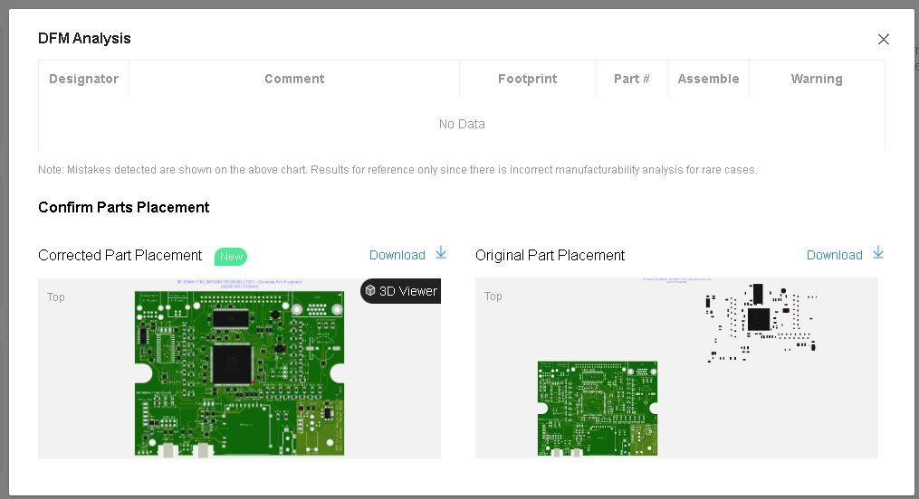
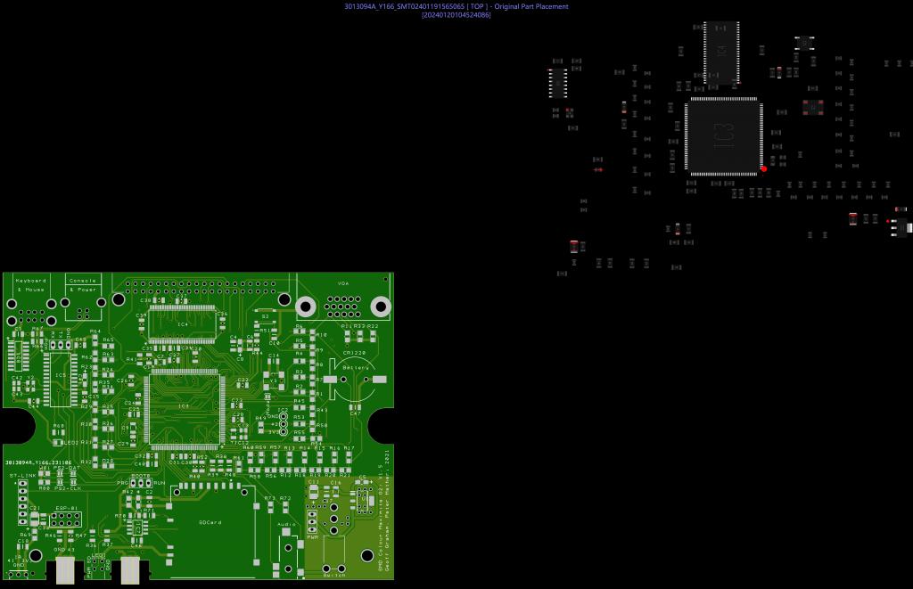
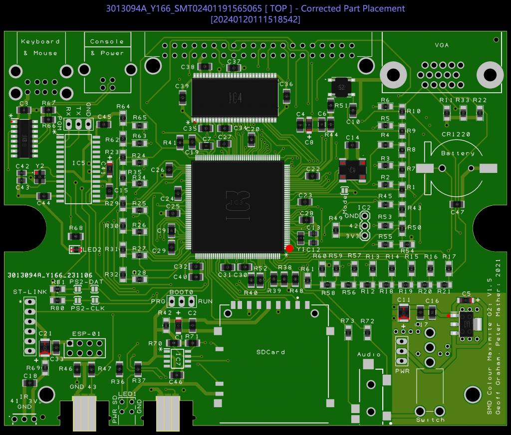
In the PCB's I get made at JLC, the computer always puts the SDRAM chip either 90 degrees or 180 degrees out of alignment. During the production process, JLC engineers correct that for me, and they always arrive with the SDRAM chip aligned correctly. You can check the alignment just after payment, by clicking on "DFM Analysis" in your PCBA part of the order. This only shows up in your order as a clickable link, AFTER the engineers have checked and corrected any alignment issues. That shows the original computer alignment, and the JLC engineer-corrected alignment. In any event, I have never had a problem, and JLC always supply the boards with the correct component alignment in my experience, and they have made hundreds of CMM2 G2 boards for me at this point. Smoke makes things work. When the smoke gets out, it stops! |
||||
| CtrlAltSockPuppet Newbie Joined: 05/01/2024 Location: United KingdomPosts: 11 |
Interesting Grogster. Mind if I ask what you do with so many boards? |
||||
Grogster Admin Group Joined: 31/12/2012 Location: New ZealandPosts: 9307 |
I sell them via my website.  JLC assembles the top of the board SMD-wise, and when I get them, I fit all the through-hole sockets etc, program and test the board, put it in a case, and flick it off to whoever orders them. EDIT: Here is an example of the DFM Analysis....   Note apart from total misalignment of ENTIRE parts placement, the SD RAM chip is 90 degrees out.  This is the image of the corrected placement by the JLC engineers. I do not need to ask for this, they just do it automatically, cos they can see it is not right. I guess they have a whole team of people that just check the component placements for PCBA... Edited 2024-01-21 14:24 by Grogster Smoke makes things work. When the smoke gets out, it stops! |
||||
| matherp Guru Joined: 11/12/2012 Location: United KingdomPosts: 9115 |
Grogster, the latest download from Geoff's site should be completely correct with no changes needed |
||||
Grogster Admin Group Joined: 31/12/2012 Location: New ZealandPosts: 9307 |
Thanks for the heads up - will go download it. In any event, JLC seem to be able to work it out on their own.   Smoke makes things work. When the smoke gets out, it stops! |
||||