|

|
Forum Index : Microcontroller and PC projects : RP2040 Geek
| Page 1 of 3 |
|||||
| Author | Message | ||||
| Bernie3D Newbie Joined: 02/08/2023 Location: United StatesPosts: 19 |
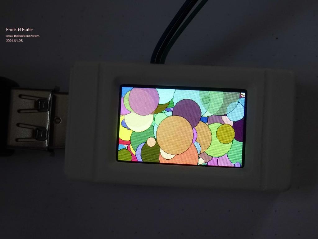
The Waveshare RP2040-Geek works fine for those that need a minimal platform to run Picomite. waveshare.com/rp2040-geek.htm The schematic is available on Waveshare's website (scroll to the bottom of their Wiki link) It has an SD card, 4MB Flash and a 240x135 IPS LCD, which appears bright and clear. It works with OPTION LCDPANEL ST7789_135, although the Backlight is wired to GP25, so you have to use OPTION HEARTBEAT OFF before you configure OPTION LCDPANEL. The LCD is wired to SPI2 configured in OPTION SYSTEM SPI. The SD Card is on the SPI, which needs a dedicated OPTION SD CARD definition for all the GP pins. However since the SD_CS is on GP23, you can't use Picomite v5.07.07, but will need v5.07.08 (5 Oct 2023) and beyond, which has the OPTION PICO OFF to free up GP23. I'm sure the next official Picomite release will have this option. Anyway, besides the limited GPn breakout, the performance matches the standard Pico, and is sufficient for small projects, such as data logging to SD Card, or a small display project. Regards, Bernie Edited 2023-12-10 16:04 by Bernie3D |
||||
Grogster Admin Group Joined: 31/12/2012 Location: New ZealandPosts: 9306 |
WS impress me.  They actively develop all sorts of new boards and modules. It's almost hard to keep up with them....  Smoke makes things work. When the smoke gets out, it stops! |
||||
| Mixtel90 Guru Joined: 05/10/2019 Location: United KingdomPosts: 6787 |
I try.... ;) Mick Zilog Inside! nascom.info for Nascom & Gemini Preliminary MMBasic docs & my PCB designs |
||||
| Frank N. Furter Guru Joined: 28/05/2012 Location: GermanyPosts: 828 |
@Bernie3D: Thank you for pointing out this beautiful board! It really works fantastically!  These are my settings: OPTION HEARTBEAT OFF OPTION PICO OFF OPTION SYSTEM SPI GP10,GP11,GP28 OPTION LCDPANEL ST7789_135, LANDSCAPE,GP8,GP12,GP9,GP25 OPTION SDCARD GP23, GP18, GP19, GP20 OPTION AUDIO GP2,GP3', ON PWM CHANNEL 1 It is possible to connect COM2, PWM2 or I2C1 to the UART socket. I2C2 or PWM1 can be connected to the DEBUG socket. With the I2C/ADC socket, GP29 should be able to be used as ADC3 (not tried) - GP28 is already used for SPI MISO and therefore probably cannot be used... Frank |
||||
| Volhout Guru Joined: 05/03/2018 Location: NetherlandsPosts: 4233 |
Hi Frank, Since the LCD is most likely only an output device, can't you assign GPIO12 as MISO (OPTION SYSTEM SPI GP10,GP11,GP12), and then free up GP28 ? Volhout P.S. I ordered one too. This is the perfect laptop companion for small test applications. With the marvelous V50800 MMBasic !!! Edited 2024-01-25 20:59 by Volhout PicomiteVGA PETSCII ROBOTS |
||||
| Volhout Guru Joined: 05/03/2018 Location: NetherlandsPosts: 4233 |
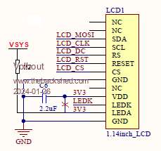
In this schematic it shows GPIO12 is used for reset of the LCD, and indeed, the MISO is not connected to the LCD. I have tested with V50800 with your OPTION settings, and PICO OFF, HEARTBEAT OFF, and you can use GPIO24 (it has SPI2_RX option, but on a standard PICO it is tied to the input voltage detector). I have no GEEK unit, so you must test yourself. GPIO24 is not used in the GEEK. RP2040-GEEK-Schematic.zip So THIS should work and free pin GP28. OPTION HEARTBEAT OFF OPTION PICO OFF OPTION SYSTEM SPI GP10,GP11,GP24 OPTION LCDPANEL ST7789_135, LANDSCAPE,GP8,GP12,GP9,GP25 OPTION SDCARD GP23, GP18, GP19, GP20 OPTION AUDIO GP2,GP3', ON PWM CHANNEL 1 Volhout Edited 2024-01-25 22:56 by Volhout PicomiteVGA PETSCII ROBOTS |
||||
| stanleyella Guru Joined: 25/06/2022 Location: United KingdomPosts: 2129 |
It reminds me of 168x80 on pico for the oscilloscope threads and that was nice device. is it sorted enough to program ie worth buying as a mini pico? I've never used debug |
||||
| NPHighview Senior Member Joined: 02/09/2020 Location: United StatesPosts: 200 |
I've just ordered two, and will port the oscilloscope code to them when they arrive, post the code on my Github site, then post a link here. - Steve ("NPHighview") Edited 2024-01-26 12:41 by NPHighview Live in the Future. It's Just Starting Now! |
||||
| Volhout Guru Joined: 05/03/2018 Location: NetherlandsPosts: 4233 |
I have looked through the schematics, and there is little I would have done different. - I would have driven the LCD backlight from the VSYS (5V) and not from 3.3V. a/ it heats up the voltage regulator U1 (SOT23) b/ When PWM control is used is causes ripple on the 3.3V that may cause ADC errors.  - I would have added a 3 pin header for GPIO0/GND/GPIO1. These are currently not used. When I get my unit I will see that I can make these modifications. But even without modifications, it is a nice design.... Volhout Edited 2024-01-26 17:41 by Volhout PicomiteVGA PETSCII ROBOTS |
||||
| Frank N. Furter Guru Joined: 28/05/2012 Location: GermanyPosts: 828 |
@Volhout: Thanks for the tip - does it really work? The manual says: And the following command for the second channel (referred to as SPI2) is: SETPIN rx, tx, clk, SPI2 Valid pins are RX: GP8, GP12 or GP28 TX: GP11, GP15 or GP27 CLK: GP10, GP14 or GP26 I thought you couldn't use GP24??? It would be great if this works - I'll give it a try! Is there actually the possibility of a "software SPI port"? Too bad that the board has no buttons (except the BOOT button) and only so few pins are led out!!! Frank |
||||
| Volhout Guru Joined: 05/03/2018 Location: NetherlandsPosts: 4233 |
Hi Frank, According the RP2040 chip datasheet And the good thing is that Peter implemented these alternate functions in MMBasic, despite the fact that this pin is not able to use that alternate function on a genuine Pico board. That is why I tested it (on a genuine board) with V50800, to see if MMBasic would accept defining GPIO24 as MISO. But I am not sure what happens in a GEEK when you define GPIO24 as MISO for the display, and the pin is not connected to anything (floating). Can you run the LCD.? Regards, Volhout PicomiteVGA PETSCII ROBOTS |
||||
| atmega8 Guru Joined: 19/11/2013 Location: GermanyPosts: 722 |
17,90€ Amazon Germany @Frank N. Furter wher did you order it? |
||||
| Frank N. Furter Guru Joined: 28/05/2012 Location: GermanyPosts: 828 |
Hi Volhout, I have tried your settings and can confirm that the LCD works! THANK YOU! Another pin regained!     @atmega8: I bought it from Botland ( https://botland.de/rp2040-mikrocontroller-boards/23878-rp2040-geek-entwicklungsplatine-114-farb-lcd-display-waveshare-25394.html ) - I hate Amazon! I paid 16,89€ (including shipping) - It arrived within two days from Poland (it is a Polish store). Frank |
||||
| Volhout Guru Joined: 05/03/2018 Location: NetherlandsPosts: 4233 |
Hihi.... Just for fun: put PicoMite_VGA firmware in it ,and you can use it with a VGA monitor. GP2,3,4,5 can be set for RGB, and GP28,29 as HSYNC/VSYNC. Thanks to V50800 configurable VGA pins. Run PETSCII ROBOTS on it. But I am targetting this for some new projects: - A I2C spy (listen in on a I2C bus and decode what you are seeing) Just some PIO code, and small PicoMite program, and larger PC (MMB4W) program. - A 32 channel 8MHz logic state/timing analyzer (so you can debug Commodore 64 (6502/Z80) software). Plan is to make this configurable: 32x8MHz/16x16MHz/8x32MHz/4x64MHz Will require external HW to get 32 inputs. Some PIO code, small PicoMite program, larger MMB4W application. This will use much of the PIO code from PicoLA. Enough plans.... And every day new idea's come up. I may change my mind 10x before it arrives (I ordered Waveshare direct from China, so that will take more than 2 days). It has 4Mb flash, does that imply that the A: drive is 2.8Mbyte ? Volhout Edited 2024-01-26 20:30 by Volhout PicomiteVGA PETSCII ROBOTS |
||||
| Frank N. Furter Guru Joined: 28/05/2012 Location: GermanyPosts: 828 |
> ? MM.INFO(free space) 2887680    Frank |
||||
| stanleyella Guru Joined: 25/06/2022 Location: United KingdomPosts: 2129 |
doh moment, sorry. waveshare rpi2040 £11 odd with postage. ordered one Edited 2024-01-27 04:52 by stanleyella |
||||
| stanleyella Guru Joined: 25/06/2022 Location: United KingdomPosts: 2129 |
interesting. why not. The colour display nice. waveshare sweeties are hard to resist. Of course I need one :) I just recovered the 160x80 on a pico thanks to phil99 and thinking of using polygon to draw the oscilloscope display. polygon don't need the ends joined it seems now?? I'll try, until the 2040 geek arrives. stan Edited 2024-01-29 06:02 by stanleyella |
||||
| NPHighview Senior Member Joined: 02/09/2020 Location: United StatesPosts: 200 |
I just received two of the Waveshare RP2040-Geek boards. Originally, I was concerned that I wouldn't be able to find connectors for the three ports on the side of the enclosure, but they're included, with female-terminated wires (with GND:black, 3.3V:red, and signals blue, green, orange, and yellow). It's pretty easy to figure out which is which. The little enclosures snap apart readily, but the Reset button cover sproings out - keep an eye on it :-) Volhout's recommended OPTION configuration works wonderfully! With those, all of the necessary connections are there for my dual-trace scope code, but I haven't yet got all the kinks out (it looks like the ADC input channels may be scaled differently than on the "plain" RP2040 boards). So far, overclocking to 266,000 works fine. As I finish up code, I'll post links to my GitHub. Live in the Future. It's Just Starting Now! |
||||
| Bleep Guru Joined: 09/01/2022 Location: United KingdomPosts: 509 |
I got mine on Ebay, quick delivery and not overpriced at £12.30. I installed the latest MMBasic and tested at 378MHz with the above options, all looking great. The display looks much better than the photo would have you beleive. :-) Regards Kevin. Edited 2024-02-06 04:41 by Bleep |
||||
| stanleyella Guru Joined: 25/06/2022 Location: United KingdomPosts: 2129 |
still waiting for mine to arrive  Arrived today. found left on doorstep in rain though I was in all day. It works. Edited 2024-02-07 04:47 by stanleyella |
||||
| Page 1 of 3 |
|||||