
|
|
Forum Index : Microcontroller and PC projects : picomite (non VGA)
| Author | Message | ||||
| Mixtel90 Guru Joined: 05/10/2019 Location: United KingdomPosts: 5727 |
The SD card socket is a Molex part number 104031-0811. It has 8 pins and is push-pull. I originally got them from ebay, but they are also available from Farnell (part 2678573) and AliExpress. I think all the larger distributers have them too. Mick Zilog Inside! nascom.info for Nascom & Gemini Preliminary MMBasic docs & my PCB designs |
||||
| okwatts Regular Member Joined: 27/09/2022 Location: CanadaPosts: 51 |
Hi All I am totally bamboozled by this behaviour so it must mean there is a glaringly obvious issue I am not seeing. I have been trying to get the SDcard setup on one of Mixtel90's little boards for the RP2040-Zero (thanks to lizby). I carefully separated a board, install the cap C1 (10ufd) and R1 (through-hole 10R). Dutifully soldered the boards together and setup the SDCARD as option sdcard GP13,gp10,gp11,gp12. When I insert a card that has been in my picomiteVGA (Peter's ver1.0a) I get the message "SDCard not found". Okay I made an error and touched up the soldering all round, same problem. After a few days of this I figure I must have a dud rp2040ZERO or I screwed up the sdcard holder. Desolder everything. I decide to try another RP2040-zero but this time I have a micro sd module that is commonly used for arduino. Using dupont wires I try this on the new RP2040-zero, same problem. I keep going round the loop no satisfaction. Okay I think maybe it's a problem with the RP2040-zero and take a genuine pico install 5.08.0 and setup the card using the same GP ports- result same message. Now I try a different micro SD card from a Raspberry Pi. Now it says "this is not a FAT volume" and when I remove the sdcard I get the message "Warning SD Card removed". At this point I know the card is detected but I am still not getting a listing of the files. (I have been putting it back in the PicomiteVGA just to make sure it can still be read there - no problem). So I am totally confused by this behaviour and I am reminded of the saying "repeating the same thing and expecting a different result is insanity". So I feel like I am really going nuts. I need some fresh insight and am hoping someone can point me in the right direction. Then I'll have another go with rp2040-Zero and the little daughter board. |
||||
| phil99 Guru Joined: 11/02/2018 Location: AustraliaPosts: 1783 |
I am guessing C1 is across the SD supply pins and R1 is in series with the supply. If so try reducing R1 to 2.2Ω, or bridge it out if you don't have one. Some SD cards are more fussy about the supply than others. |
||||
| Mixtel90 Guru Joined: 05/10/2019 Location: United KingdomPosts: 5727 |
R1 is probably way too high. The usual value is 2R2 - although a dead short is usually fine for microSD cards in my experience. Try shorting out R1. Mick Zilog Inside! nascom.info for Nascom & Gemini Preliminary MMBasic docs & my PCB designs |
||||
| okwatts Regular Member Joined: 27/09/2022 Location: CanadaPosts: 51 |
Okay I tried some things. When I used a different sdcard in my setup with the external sd module and both the picomite and RP2040-zero it was recognized and I could see a list of files. When I reverted to my previous sdcard used in Peters PicomiteVGA it was not seen. So there is a difference in the 2 sd cards. Okay so I reassembled Mixtel90's sd daughter board (replacing the 10R resistor with a jumper) and the RP2040-Zero and I had no joy with either sdcard. I then traced out the daughter card and I believe there is no ground connection from the ground pin to the sdcard. I would like Mixtel90 or lizby to verify that. I tried a jumper from the ground pin to the case of the sdcard holder and this is with a loose fit of the 2 cards (I didn't want to have to solder and desolder the cards again) so the connection may be sketchy. In any event that didn't make either of the cards visible to MMBasic. At this point I am taking a break from this project and will await more feedback. |
||||
| Mixtel90 Guru Joined: 05/10/2019 Location: United KingdomPosts: 5727 |
I've just dug the design files out. There *is* a missing GND, but it's not the SD card. It's from the Zero's GND pin, which is isolated. Unfortunately C1 is grounded to one side and the SD card is grounded to the other, which makes things a little awkward. Try a wire link from the Zero's GND to any GND or metal shell on the SD card socket. It will probably work then. Grounding C1 is more awkward as it is sandwiched between the Zero and the board and there are no other GND points on that side. It would be easy to put another capacitor underneath though If you can scrape the solder mask away on the top side adjacent to the Zero's GND you may be able to solder blob it though. Sorry 'bout that. It was my deliberate mistake to see who was awake. That's my story and I'm sticking to it. :) Mick Zilog Inside! nascom.info for Nascom & Gemini Preliminary MMBasic docs & my PCB designs |
||||
| okwatts Regular Member Joined: 27/09/2022 Location: CanadaPosts: 51 |
Just an update to say that I ran jumpers and tried out this with dupont wires and this worked. Pictures below and then reassembled as a sandwich and managed to keep it working (lots of desoldering, resoldering etc.) 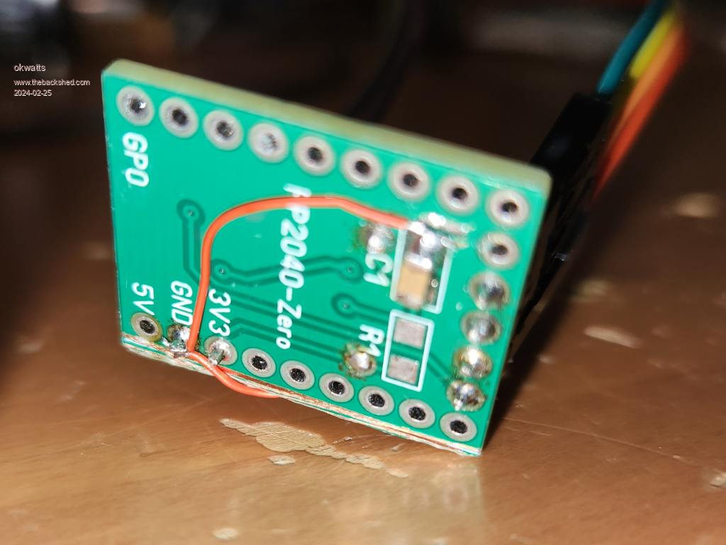 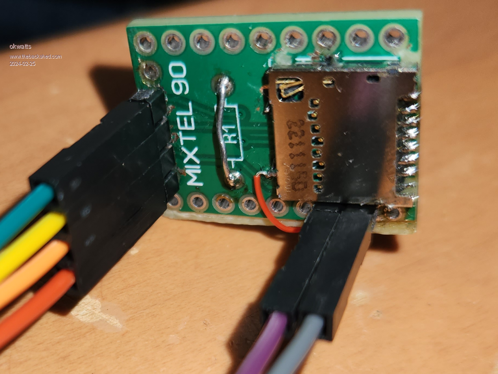 Finally together as intended. 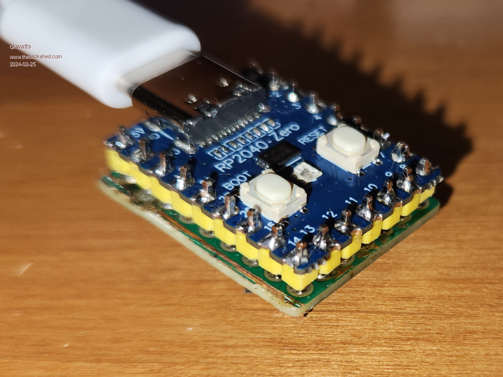 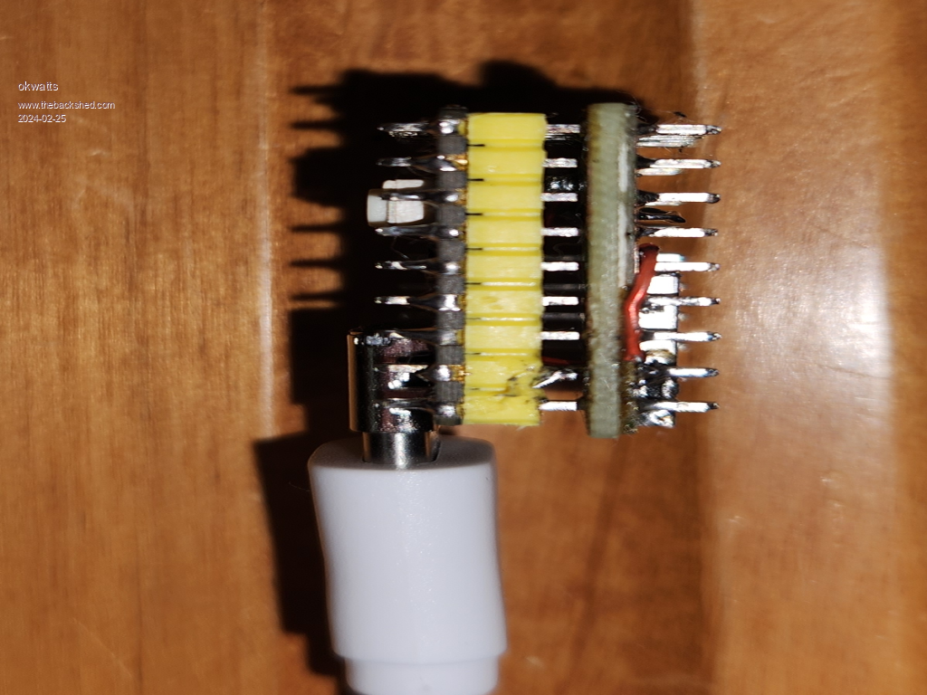 |
||||
| lizby Guru Joined: 17/05/2016 Location: United StatesPosts: 3015 |
Thanks for posting. I'll try to get mine working soon. PicoMite, Armmite F4, SensorKits, MMBasic Hardware, Games, etc. on fruitoftheshed |
||||
| Mixtel90 Guru Joined: 05/10/2019 Location: United KingdomPosts: 5727 |
Thanks for the pics! I love seeing my designs built up by others. It's encouraging. :) @ lizby It'll be a lot easier now you know to put the GND links in before soldering everything together. :) Mick Zilog Inside! nascom.info for Nascom & Gemini Preliminary MMBasic docs & my PCB designs |
||||
| PhenixRising Senior Member Joined: 07/11/2023 Location: United KingdomPosts: 284 |
Hi Mick. Haven't kept-up with the Picomite (ARMmite H7 been getting my attention). Does this solve a problem re: flaky ADCs that I seem to remember? Or some other benefit? |
||||
| Volhout Guru Joined: 05/03/2018 Location: NetherlandsPosts: 3529 |
Somebody already did it... rp2040 and sd card ... Volhout PicomiteVGA PETSCII ROBOTS |
||||
| Mixtel90 Guru Joined: 05/10/2019 Location: United KingdomPosts: 5727 |
Nope. The ADC problem is on the die of the RP2040 chip itself. Unless they change the die that fault won't go away. :( There is a slight advantage to using a linear regulator, it reduces supply line noise to the ADC. That helps a little when reading low levels with the ADC. It helps quite a bit in audio applications. You do lose out on supply flexibility though as your minimum supply voltage is 3V3 + the volt drop in the regulator (about 0.15V in this case). Also it is less efficient than a switcher, making it less useful for battery operation. Mick Zilog Inside! nascom.info for Nascom & Gemini Preliminary MMBasic docs & my PCB designs |
||||
| Mixtel90 Guru Joined: 05/10/2019 Location: United KingdomPosts: 5727 |
Ah, but mine's breadboard-friendly - and doesn't take up much space on the breadboard either. :) It's also cheap. Mick Zilog Inside! nascom.info for Nascom & Gemini Preliminary MMBasic docs & my PCB designs |
||||
| stanleyella Guru Joined: 25/06/2022 Location: United KingdomPosts: 1643 |
rpi2040 zero is not strip board friendly. probably a breakout board ae. |
||||
| Mixtel90 Guru Joined: 05/10/2019 Location: United KingdomPosts: 5727 |
*My* board is. I used the end pins for the micro SD card and you don't need any headers projecting beneath the board there. Providing your "side" header pins are long enough (or you use 0.4mm or 0.5mm wire instead of pins) you can plug it into a normal breadboard. Mick Zilog Inside! nascom.info for Nascom & Gemini Preliminary MMBasic docs & my PCB designs |
||||
