
|
|
Forum Index : Microcontroller and PC projects : picomite (non VGA)
| Page 1 of 2 |
|||||
| Author | Message | ||||
| zeitfest Guru Joined: 31/07/2019 Location: AustraliaPosts: 683 |
I am after small boards that just have the pico and sd micro socket. Is the non-VGA picomite still current ? I can't see any suppliers or Silicon Chip kit/pcb etc. |
||||
| lizby Guru Joined: 17/05/2016 Location: United StatesPosts: 3789 |
Easy to wire up: Seeed RP2040 with micro SD reader Mick posted a picture of a PCB in the post following the above linked, but I don't think he posted the gerbers. Perhaps he could if you wanted. PicoMite, Armmite F4, SensorKits, MMBasic Hardware, Games, etc. on FOTS |
||||
| Mixtel90 Guru Joined: 05/10/2019 Location: United KingdomPosts: 8913 |
It's still current. :) I still have the drawing for that tiny board if you want it, but there's no problem in rustling a custom job up. Mick Zilog Inside! nascom.info for Nascom & Gemini Preliminary MMBasic docs & my PCB designs |
||||
| zeitfest Guru Joined: 31/07/2019 Location: AustraliaPosts: 683 |
Thanks, I am thinking a specific design pcb may be best, some time down the track. ATM I am using a pico with the sd adaptor hanging on wires, and/or the SC backpack. Maybe the backpack without the audio and adding a good A/D and circuit via I2c or spi... next year maybe  |
||||
| Volhout Guru Joined: 05/03/2018 Location: NetherlandsPosts: 5953 |
Mick, I like the ultra small sd card connector board. Not sure if the pinout allows, but if you could move the sd card pins (SPI) to the perpendicular row, the breadboard friendly parallel pin rows would be free. Then move the resistor and cap to the card reader side. Then you could sandwich the 2 boards, especially when the board is 0.8 or 1mm thick, and even use 2.54mm pin headers to make the sandwich breadboard friendly. Volhout Edited 2023-12-11 02:35 by Volhout PicomiteVGA PETSCII ROBOTS |
||||
| Mixtel90 Guru Joined: 05/10/2019 Location: United KingdomPosts: 8913 |
That's more or less how it is. The uSD card is on: CS - GP13 MISO - GP12 MOSI - GP11 SCLK - GP10 GP9, also along the end, isn't used. Neither are both the 9-pin sides. The resistor & cap come off 3V3, of course, and are tucked between the rear of the uSD and the end pins. The uSD. They are shown between the Zero and the pcb, but can easily be on the bottom with the uSD. I've just realized that you have to be careful with the RP240-Zero. In spite of it having castellated contacts you can't SMD it unless you cut a big hole in your PCB as the RP2040 (and most of the rest) is on the bottom of the board. If you want a breadboard friendly arrangement you need to use long headers. It mounts quite neatly upside down on normal headers, but you can't get to the LED and buttons then... Some major re-thinking on my controllers might be in order (although I think I'm ok for space on those). I've just had a play and, in theory, you could fit normal headers, use a thin pcb and fit the uSD between the pcb and the Zero. However, you'd need a small small SMD resistor and cap to keep the thickness down. Too fiddly for me. Would you like me to arrange several of these on a strip? If they are only separated by silkscreen and you cut them yourself there's no extra charge. I can leave a mm or so between them for cutting. Edited 2023-12-11 04:02 by Mixtel90 Mick Zilog Inside! nascom.info for Nascom & Gemini Preliminary MMBasic docs & my PCB designs |
||||
| homa Guru Joined: 05/11/2021 Location: GermanyPosts: 631 |
.jpg) https://www.sparkfun.com/products/17745 Too expensive for my taste, though. |
||||
| phil99 Guru Joined: 11/02/2018 Location: AustraliaPosts: 3296 |
Early in PicoMite development Peter glued a SMD micro SD socket over the logo of a standard Pico. Soldering thin enameled wire to the socket pins needs good eyes and steady hands. |
||||
| Mixtel90 Guru Joined: 05/10/2019 Location: United KingdomPosts: 8913 |
So, four to a strip gets you 20 boards per order. :) 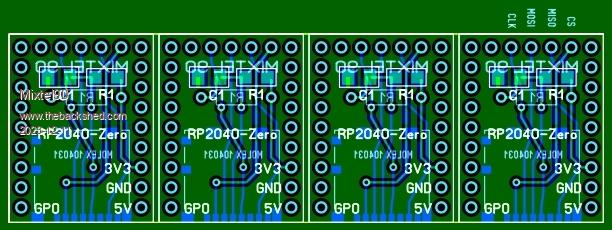 I've tweaked it a bit. The resistor can be a SMD part if you wish. If so, it fits on top of the board and tucks in near the RP2040. A standard resistor can be fitted below the board, behind the uSD socket. The uSD is actually connected to a hardware SPI, but that doesn't matter. I did it just because I could. :) Mick Zilog Inside! nascom.info for Nascom & Gemini Preliminary MMBasic docs & my PCB designs |
||||
| al18 Senior Member Joined: 06/07/2019 Location: United StatesPosts: 241 |
This microSD breakout board should work fine with the Pico $1.96 on eBay https://www.ebay.com/itm/224067263348?hash=item342b731b74:g:3EQAAOSwHP9iS3gR |
||||
| lizby Guru Joined: 17/05/2016 Location: United StatesPosts: 3789 |
That has worked for me, but some have found that in some circumstances, the resistors interfere with successful operation. PicoMite, Armmite F4, SensorKits, MMBasic Hardware, Games, etc. on FOTS |
||||
| Mixtel90 Guru Joined: 05/10/2019 Location: United KingdomPosts: 8913 |
That one is ok, but ignore the specification in the advert. There is no level shifting and if you put 5V on it you'll blow your SD card up. There are simple pullup resistors and two paralleled supply decoupling capacitors. In theory you shouldn't have the pullups, but they don't seem to do any harm. The board I've shown uses a SMD holder rather than a module. It's fiddly to solder but I've done a few now. :) I use a pointed tip - one of the 5W USB irons is good for this. Mick Zilog Inside! nascom.info for Nascom & Gemini Preliminary MMBasic docs & my PCB designs |
||||
| Mixtel90 Guru Joined: 05/10/2019 Location: United KingdomPosts: 8913 |
Finally got round to doing the gerbers. Sorry about the delay. :) RP2040-Zero + uSD.zip Mick Zilog Inside! nascom.info for Nascom & Gemini Preliminary MMBasic docs & my PCB designs |
||||
| lizby Guru Joined: 17/05/2016 Location: United StatesPosts: 3789 |
Ordered--$4US for 20. Note that I had to replace/remove the "+" in the file name--JLCPCB didn't like it. If anyone in the U.S. or Canada would like 1 or 2, PM me your address. After I test one, I'll mail them out. No charge--for the good of the MMBasic crew. Slow boat from China, so it will be several weeks. Thanks, Mick, for all your good work. PS: If you haven't ordered any, Mick, PM me your address and I'll send you a stick. ~ Edited 2023-12-12 06:19 by lizby PicoMite, Armmite F4, SensorKits, MMBasic Hardware, Games, etc. on FOTS |
||||
| lizby Guru Joined: 17/05/2016 Location: United StatesPosts: 3789 |
Mick--I received the PCBs. Slow boat was slower than usual for JLCPCB. What are the values for C1 and R1? PicoMite, Armmite F4, SensorKits, MMBasic Hardware, Games, etc. on FOTS |
||||
| phil99 Guru Joined: 11/02/2018 Location: AustraliaPosts: 3296 |
They are the SD card supply filter. The usual values are 10uF+ and 0R to 2R2. Edit For through-hole C1 tantalum or low ESR electrolytic, for SMD ceramic chip. Edited 2024-01-03 09:58 by phil99 |
||||
| Mixtel90 Guru Joined: 05/10/2019 Location: United KingdomPosts: 8913 |
The micro SD cards seem to be far less critical than the bigger ones. I've often used them without any decoupling but I included it to play safe. :) If you want to live life on the edge too, omit C1 and short out R1. Somewhere between 1R0 and 10R for the resistor and 100nF upwards for the capacitor. As Phil says, there's no reason not to use 2R2 and 10uF unless you can't get them for some reason. Incidentally, C1 is a 1206 size SMD component and R1 can be either a through-hole or a 1206. There's no room for a through-hole cap really. The SD card socket is on the bottom of the board, R1 & C1 are on the top. They should just tuck behind the components on the bottom of the RP2040-Zero. Mick Zilog Inside! nascom.info for Nascom & Gemini Preliminary MMBasic docs & my PCB designs |
||||
| zeitfest Guru Joined: 31/07/2019 Location: AustraliaPosts: 683 |
I gather these stack onto pi zero boards ? very compact, looks well done.. don't know much about pi zero though, is it a direct substitute for pico ? |
||||
| Mixtel90 Guru Joined: 05/10/2019 Location: United KingdomPosts: 8913 |
They fit underneath the RP2040-Zero (not the Raspberry Pi Zero). It's almost the same as the standard Pico, but with a linear regulator, USB-C connector, WS LED, reset button and less GPIO pins. Unfortunately the pins needed to run it as a PicoMite VGA are missing. This board uses the pins across the end of the board for the SD card so they aren't wasted when you want to plug just the two side rows into something. They are also reasonably priced from AE - and rather fun to use because they are so cute. :) The ordinary PicoMite firmware runs on them perfectly. Mick Zilog Inside! nascom.info for Nascom & Gemini Preliminary MMBasic docs & my PCB designs |
||||
| lizby Guru Joined: 17/05/2016 Location: United StatesPosts: 3789 |
Well, I have two different micro SD sockets, and neither one is right. What is the correct part number for this, and from whom? PicoMite, Armmite F4, SensorKits, MMBasic Hardware, Games, etc. on FOTS |
||||
| Page 1 of 2 |
|||||
| The Back Shed's forum code is written, and hosted, in Australia. | © JAQ Software 2026 |
