|

|
Forum Index : Microcontroller and PC projects : kick my. mcp expander fail
| Author | Message | ||||
| stanleyella Guru Joined: 25/06/2022 Location: United KingdomPosts: 2129 |
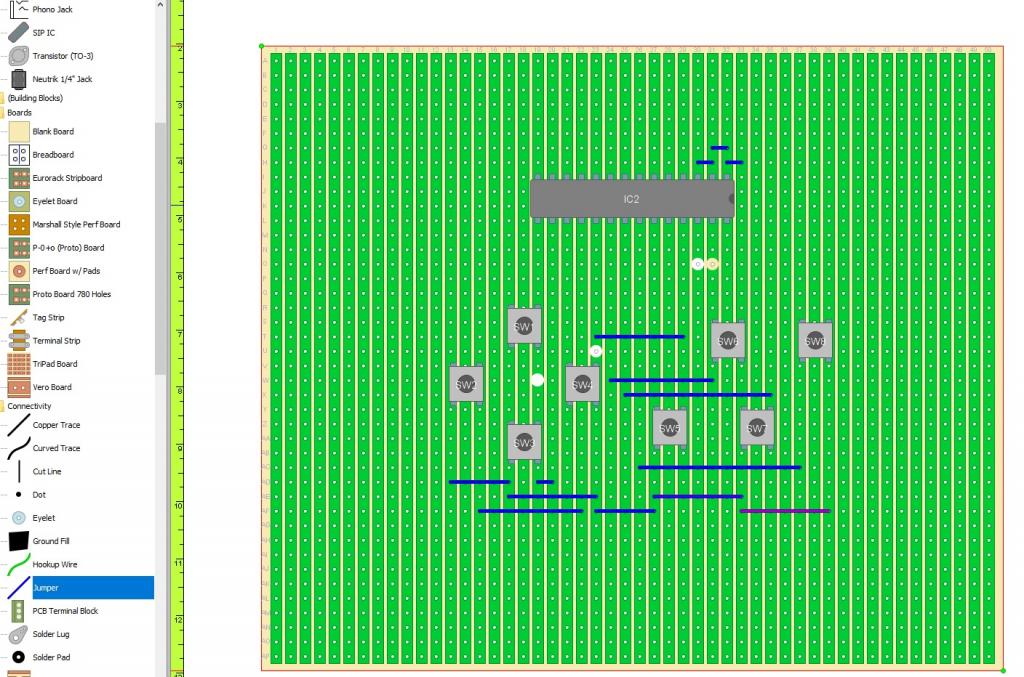
I built a mcp23017 expander and wired all the buttons 90 degrees the wrong way. Please form an orderly queue to kick some sense. I wondered why the buttons didn't fit stripboard designer progs. doh. anyone else mess up stupid? |
||||
| stanleyella Guru Joined: 25/06/2022 Location: United KingdomPosts: 2129 |
I think the vga keyboard that is 2 wires I should try with lcd. mcp23017 total rewire.I'm thick. thought it be a nice in-out board I'll try again. |
||||
| phil99 Guru Joined: 11/02/2018 Location: AustraliaPosts: 2135 |
Too many times to list... even if I could remember them. Seniors Moments every day now. Edited 2023-11-24 09:38 by phil99 |
||||
Chopperp Guru Joined: 03/01/2018 Location: AustraliaPosts: 1057 |
Ditto to phill99 ChopperP |
||||
vegipete Guru Joined: 29/01/2013 Location: CanadaPosts: 1109 |
I've messed up those tact switches often enough that I make sure I always wire them up on diagonally opposite corners. Then the 90 degrees doesn't matter. Visit Vegipete's *Mite Library for cool programs. |
||||
Quazee137 Guru Joined: 07/08/2016 Location: United StatesPosts: 571 |
Yup it happens to us all over time.  20 boards with 32 SMD transistors placed PNP instead of NPN. (hand soldered  ) ) I miss labeled the two reals. Had to check all part reals used to be sure I hadn't miss labeled the resistors and the caps. Quazee137 Ditto to phill99 & ChopperP Edited 2023-11-24 17:35 by Quazee137 |
||||
| Mixtel90 Guru Joined: 05/10/2019 Location: United KingdomPosts: 6798 |
I can never remember how they work either - I end up metering one out to check. :) "It's not logical, Captain" Mick Zilog Inside! nascom.info for Nascom & Gemini Preliminary MMBasic docs & my PCB designs |
||||
| Volhout Guru Joined: 05/03/2018 Location: NetherlandsPosts: 4241 |
Autsch!!! That hurts. 640 parts to be replaced. That is a whole day of work... PicomiteVGA PETSCII ROBOTS |
||||
| stanleyella Guru Joined: 25/06/2022 Location: United KingdomPosts: 2129 |
Using DiyLayoutCreator and like vcad, the buttons align if the right way round. I don't know about placing buttons diagonally??  |
||||
| Andy-g0poy Regular Member Joined: 07/03/2023 Location: United KingdomPosts: 56 |
My repeating mistake, is pull ups (or lack of) on interrupt pins or inputs. Older MCP did not have programmable pull-ups, so you had to physically add them. One of the early PIC MUC's I used. Built a vivarium controller for a friend and it worked fine in testing, UNTIL one of the control lines switched.Then the system froze... Several hours of code debugging later, I was getting annoyed. I poked my finger at the PIC and said something rude. Well it started to work! When the control line switched again the PIC stopped. Carefully I pointed my finger at the PIC and sure enough it restarted,. No contact with the PIC was required, just poke the finger to about 1cm of the PIC... The control line pin was next to the reset pin when the control line changes state, there was enough leakage to put the PIC into a hold. Point at the reset pin and the charge was be drawn away and the PIC continued as normal. I try top remember to double check such things, but I've been caught out more than once. |
||||
| stanleyella Guru Joined: 25/06/2022 Location: United KingdomPosts: 2129 |
got a tube of 5 16bit expanders and only used for output so will test input pullups. nice chip. |
||||
| lizby Guru Joined: 17/05/2016 Location: United StatesPosts: 3150 |
Buttons aren't placed diagonally--diagonally opposite pins are connected, making sure that you cannot be connecting to two pins which are already internally connected. PicoMite, Armmite F4, SensorKits, MMBasic Hardware, Games, etc. on fruitoftheshed |
||||
| stanleyella Guru Joined: 25/06/2022 Location: United KingdomPosts: 2129 |
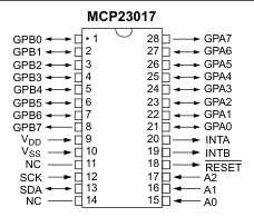
ncp23017 seems handy for 8 switches or on off and 8 outputs for just leds to show inputs. just 2 pins, sck,sda. |
||||
| Turbo46 Guru Joined: 24/12/2017 Location: AustraliaPosts: 1611 |
Stan, Please remember: Stan, Please note that for later versions of that chip the I/O arrangement has changed. GPA7 and GPB7 are output only. You may have to use two ports if you have eight switches.  You may not have 8 inputs on one port. Bill Keep safe. Live long and prosper. |
||||
bigmik Guru Joined: 20/06/2011 Location: AustraliaPosts: 2914 |
Hi all, That is exactly the approach I have used for years and indeed I used in the layout of the Game★Mite PCB. Expanding on Vegipete’s description the trick is to wire the 2 connections on diagonally opposed pins as then no matter which way the switch is plonked into the PCB the switch will always be ‘correct’ way around. Kind Regards, Mick Mick's uMite Stuff can be found >>> HERE (Kindly hosted by Dontronics) <<< |
||||
| al18 Senior Member Joined: 06/07/2019 Location: United StatesPosts: 205 |
Information on a PicoMite board that has a MCP23017 including test programs http://land-boards.com/blwiki/index.php?title=PiPicoMite01#BASIC_Interpreter |
||||
| Mixtel90 Guru Joined: 05/10/2019 Location: United KingdomPosts: 6798 |
Apparently the problem with A7 and B7 on the MCP23017 has always been there. They've recently updated the data sheet, that's all. Yes, you *might* be able to use them as inputs but it depends on the phase of the moon. This seems to have been a buggy chip for a long time. The SPI version is ok (or at least better) it seems. . Edited 2023-11-25 23:16 by Mixtel90 Mick Zilog Inside! nascom.info for Nascom & Gemini Preliminary MMBasic docs & my PCB designs |
||||