|

|
Forum Index : Microcontroller and PC projects : Pico Power Supply Cheat Sheet
| Page 1 of 3 |
|||||
| Author | Message | ||||
| aFox Regular Member Joined: 28/02/2023 Location: GermanyPosts: 76 |
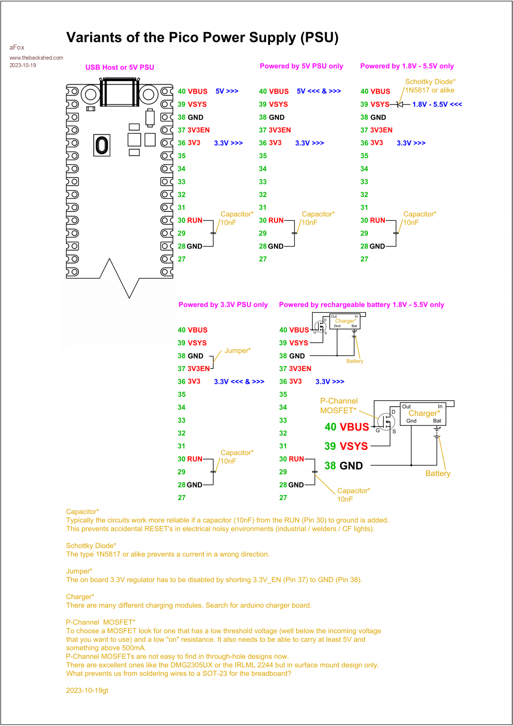
Hi Many thanks for your support. Here is the result. In conjunction with an ESP32 I got the suggestion to use the P-Channel MOSFET IRLML 2244. Whould be nice if someone could check the datasheet. Does the P-Channel MOSFET need any resistors? Suggestions are welcome. Gregor  Pico Power Supply Cheat Sheet 2023-10-19.zip Edited 2023-10-19 10:08 by aFox |
||||
| Mixtel90 Guru Joined: 05/10/2019 Location: United KingdomPosts: 6798 |
No, you don't have to have resistors for the MOSFET. When powering via VSYS the external Schottky diode is only needed if: a) The external supply is a battery, in which case it prevents it from being charged by the 5V USB input. Note that VBUS is directly connected to the USB 5V rail. or b) The external supply normally has a lower voltage than 5V. It could be from, say, a 3.3 regulator that is part of another system. The PicoMite needs at least 1.8V to run the on-board switching supply so, if you are using an external Schottky diode, you need your external supply to be at least 1.8 + 0.4 = 2.2V to be safe. Mick Zilog Inside! nascom.info for Nascom & Gemini Preliminary MMBasic docs & my PCB designs |
||||
| lizby Guru Joined: 17/05/2016 Location: United StatesPosts: 3150 |
Good summation. Thanks for posting this. Could be manual-worthy as another appendix. PicoMite, Armmite F4, SensorKits, MMBasic Hardware, Games, etc. on fruitoftheshed |
||||
| aFox Regular Member Joined: 28/02/2023 Location: GermanyPosts: 76 |
Good to know. The external Schottky diode is therefore not needed if the external supply continuously supplies a voltage of more than 5 V. It seems to be the only use case. That is a good hint! Gregor |
||||
| Mixtel90 Guru Joined: 05/10/2019 Location: United KingdomPosts: 6798 |
Of course, you aren't supposed to use a supply of over 5.5V on any supply pin. :) The Schottky diode is half of a diode gate (the other half is an on-board diode from VBUS to VSYS). This gate powers the system from whichever voltage is the higher. In doing so it isolates the lower voltage supply. You can power up to 5V direct into VSYS, that's ok. You really need to look at the powerchain diagram for the Pico. It shows the relationship between the power pins and the switching supply. Edited 2023-10-20 00:41 by Mixtel90 Mick Zilog Inside! nascom.info for Nascom & Gemini Preliminary MMBasic docs & my PCB designs |
||||
| aFox Regular Member Joined: 28/02/2023 Location: GermanyPosts: 76 |
Hi Mick Yes, there is also a Schottky diode between VBUS and VSYS. I measured a voltage drop of 0.16V. At testing some USB power supplies I got results from 4.9V to 5.26V. 5.26V - 0.16V = 5.1V The external Schottky diode is therefore in my case not needed if the external supply continuously supplies a voltage of more than 5.1V. I do not think I should recommend avoiding the Schottky diode at all, especially since USB power supplies with far higher voltages are also in circulation. Many thanks for your help. Gregor Edit: The posts crossed each other. Edited 2023-10-20 00:51 by aFox |
||||
| Mixtel90 Guru Joined: 05/10/2019 Location: United KingdomPosts: 6798 |
If you are using the on-board switching supply to get 3V3 then the supply voltage can be very flexible. The voltage at its input can be anything between 1,8V and 5.5V and you'll still get 3V3. It's a good little chip. The only problem is that it's electrically noisy so the 3V3 rail is "dirty". Normally that doesn't matter, but if you are generating audio from PWM or need minimum noise for ADC inputs then it's better to disable it and use a 3V3 linear regulator. Mick Zilog Inside! nascom.info for Nascom & Gemini Preliminary MMBasic docs & my PCB designs |
||||
| stanleyella Guru Joined: 25/06/2022 Location: United KingdomPosts: 2129 |
Because I hear the onboard supply is noisy and I used a-d I used a 5V and 3.3v lin reg supply and 3.3V enable grounded. that's it. dim probs. |
||||
| stanleyella Guru Joined: 25/06/2022 Location: United KingdomPosts: 2129 |
Easy £1 poundland li-po rechargeable supply. |
||||
| Mixtel90 Guru Joined: 05/10/2019 Location: United KingdomPosts: 6798 |
For ordinary digital signals the switching supply is fine. As far as the ADC goes the difference is mostly important at low signal levels. In fact, you may get just as good noise reduction by fitting a LM4040-3V and using OPTION VCC 3.0 as you do by using a linear regulator, and you'll be getting better accuracy too. The only real case for a linear regulator is when using PWM to generate audio. A DAC chip has much better supply noise rejection and also gives better quality. Mick Zilog Inside! nascom.info for Nascom & Gemini Preliminary MMBasic docs & my PCB designs |
||||
| Volhout Guru Joined: 05/03/2018 Location: NetherlandsPosts: 4243 |
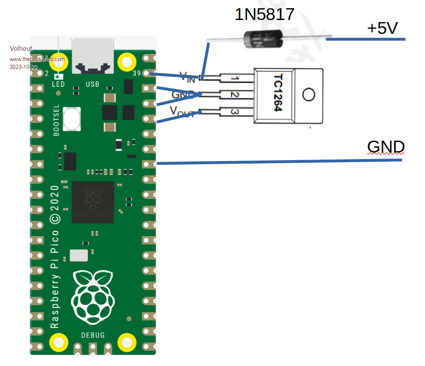
For your cheat sheet..... The 3.3V linear power supply in it's simplest form.  Edited 2023-10-20 04:01 by Volhout PicomiteVGA PETSCII ROBOTS |
||||
| stanleyella Guru Joined: 25/06/2022 Location: United KingdomPosts: 2129 |
yes Volhout... and tantalum caps on input and out put |
||||
| aFox Regular Member Joined: 28/02/2023 Location: GermanyPosts: 76 |
According to the data sheet only 1µF on the output side. Theory praxis may different. But the TC1264 is not widelyavailable. The Raspberry Foundation suggest a NCP1117 aka LD1117 with two 10µF on both sides. I think the cheat sheet needs a back cover. Gregor |
||||
| aFox Regular Member Joined: 28/02/2023 Location: GermanyPosts: 76 |
Ups Edited 2023-10-20 06:14 by aFox |
||||
| Mixtel90 Guru Joined: 05/10/2019 Location: United KingdomPosts: 6798 |
The 1117 pinout is GND-OUT-IN so it doesn't fit that diagram. It's very easy to get though. The LF33CV has the same pinout as the TC1264. Input cap can be as low as 100nF ad output cap 2uF - 10uF low ESR. . Edited 2023-10-20 07:43 by Mixtel90 Mick Zilog Inside! nascom.info for Nascom & Gemini Preliminary MMBasic docs & my PCB designs |
||||
| stanleyella Guru Joined: 25/06/2022 Location: United KingdomPosts: 2129 |
https://www.ebay.co.uk/itm/125585527673 |
||||
| Mixtel90 Guru Joined: 05/10/2019 Location: United KingdomPosts: 6798 |
I wonder if the markings come off when you wipe them with a bit of spit? :) Mick Zilog Inside! nascom.info for Nascom & Gemini Preliminary MMBasic docs & my PCB designs |
||||
| stanleyella Guru Joined: 25/06/2022 Location: United KingdomPosts: 2129 |
If you ate a chilli and a JD probably. surely, not that bad ?? (and don't call me Shirly) :) |
||||
| Mixtel90 Guru Joined: 05/10/2019 Location: United KingdomPosts: 6798 |
Shanghai's finest. What markings would you like on them, Sir? We have stencils for all the big manufacturers or we can supply them blank. ;) They might be fine though. :) Mick Zilog Inside! nascom.info for Nascom & Gemini Preliminary MMBasic docs & my PCB designs |
||||
| stanleyella Guru Joined: 25/06/2022 Location: United KingdomPosts: 2129 |
I don't know the depths of your cynicism, mine would be would it arrive. buy the same from a uk supplier at twice the price but 3 day delivery (royal mail optimism) . With ebay they always sorted duff orders for me which have been few. looks like a 7805 but 3.3v. I'll order 2 and see. they charge £12.50 for fish and chips here. |
||||
| Page 1 of 3 |
|||||