|

|
Forum Index : Microcontroller and PC projects : Explore64 Power Supply
| Author | Message | ||||
| circuit Senior Member Joined: 10/01/2016 Location: United KingdomPosts: 245 |
I have an Explore64 version 1B which lacks the later power select jumper and I need to run it off a power supply independent of the USB socket, but I need to keep the USB socket operational for the console. Is there a modification (track cut?) that allows this? |
||||
Grogster Admin Group Joined: 31/12/2012 Location: New ZealandPosts: 9308 |
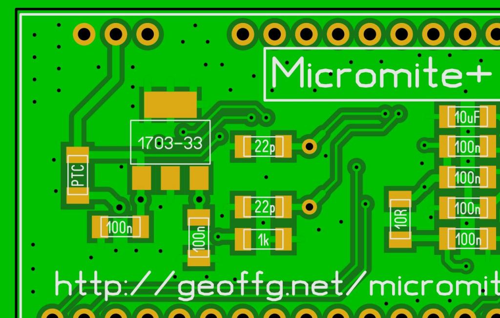
Howdy.  On the bottom of the board, to the left of the 3v3 regulator, there is a part labelled PTC - remove that, then you can connect an external 5v supply to the 5v pin at the edge of the PCB, and also still connect the USB cable, as removing the PTC, effectively cuts the link to the USB power. See image below. You WON'T be able to power the board with the USB cable if that is done, so you will ALWAYS need external power. You can replace the PTC with a SOD123 SMD power diode if you prefer - cathode to the 5v pin on the edge of the board. That effectively installs a diode-gate so you can use either external or USB power. That was how the later boards were setup.   Smoke makes things work. When the smoke gets out, it stops! |
||||
| circuit Senior Member Joined: 10/01/2016 Location: United KingdomPosts: 245 |
Thank you, that is most helpful. My main problem is that I don't have the schematic for version 1B; I have schematic versions 3 and 4 from Geoff's website and I see how the latest version has the diode in place. I had wondered about removing the polyswitch across the 5v line but I thought that this would disconnect the Vbus line for the USB interface. As USB is a differential protocol I assumed that this would incapacitate the USB comms. Your assurance that USB comms will still work with the polyswitch removed is the advice I needed. |
||||
| circuit Senior Member Joined: 10/01/2016 Location: United KingdomPosts: 245 |
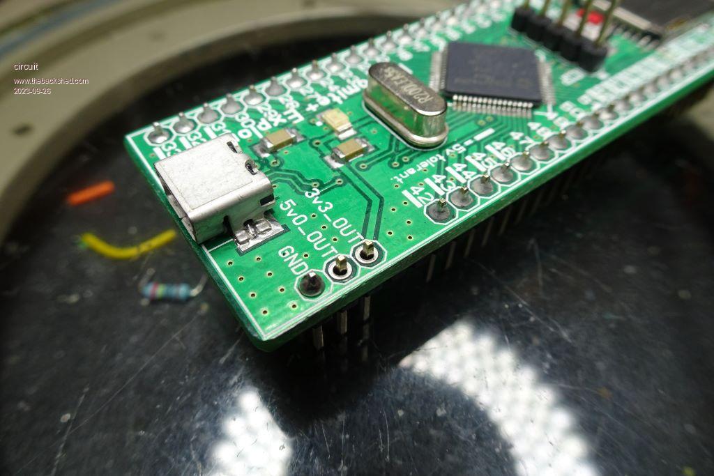
Well, this afternoon I took the advice to the workbench and removed the polyswitch. Result: a dead Explore 64! Power connected, USB line - all dead as a dodo. Frustrated, I started working around things with a meter; power line supply okay, USB fully functional with a Picomite etc. Power getting to the VCC 5v pin and then...a closer look at the Explore 64 and this is what I found:  This was a commercially-assembled Explore 64 bought as one of several units when it was in its heyday. The assembly line had somehow missed out soldering the power pins - both 3.3 out and the 5V in/out pins. Caused me half an hour of head-scratching. At least the Osiris-Rex probe has returned okay with a piece of asteroid Bennu; its predecessor (the genesis mission) crashed in the Utah desert in 2004 because the parachute failed to open. The investigation found that the gravitational sensors had been mounted upside-down! How many of you out there, dear playmates, have spent HOURS trying to track down why your new construction isn't working only to find an embarrassingly simple error that you have been staring out without actually seeing it? Next time it happens, just remember that it happens to NASA as well! Edit: quote from Scientific American; "Investigators at NASA have linked the crash of the Genesis spacecraft on September 8 to a simple design error that went undetected despite many layers of review. Either of two redundant pairs of switches could have triggered the release of a parachute when the craft hit the upper atmosphere. But because all four switches were installed backward, as specified by the Lockheed Martin design, the chute never deployed and the probe smashed into the Utah desert at more than 300 kilometers an hour. The collision destroyed the spacecraft, but scientists may eventually extract much of the data they had anticipated from the quarter-billion-dollar mission." Edited 2023-09-26 05:37 by circuit |
||||
Grogster Admin Group Joined: 31/12/2012 Location: New ZealandPosts: 9308 |
Well, that's interesting! Can I assume that once you soldered the two power pins, that NOW it is working OK as expected? I'll have a hunt for the schematic, if you still want it. Not sure where I would have filed the 1B, but I will have a hunt around in my files, and if I find it, I will upload it here. Smoke makes things work. When the smoke gets out, it stops! |
||||
| circuit Senior Member Joined: 10/01/2016 Location: United KingdomPosts: 245 |
Sorry, I should have made that clear; yes, it is working just as you advised. Thank you again for sorting me out. Regarding the schematic, I have three other Explore64 units of the same vintage and digging this particular one out for an immediate application has rather revived my interest in them. So, yes, it would be helpful to have the schematic but clearly as this one is now operational a schematic is not totally essential but would be appreciated. |
||||
Grogster Admin Group Joined: 31/12/2012 Location: New ZealandPosts: 9308 |
OK, I will see what I can find. Smoke makes things work. When the smoke gets out, it stops! |
||||
TassyJim Guru Joined: 07/08/2011 Location: AustraliaPosts: 6100 |
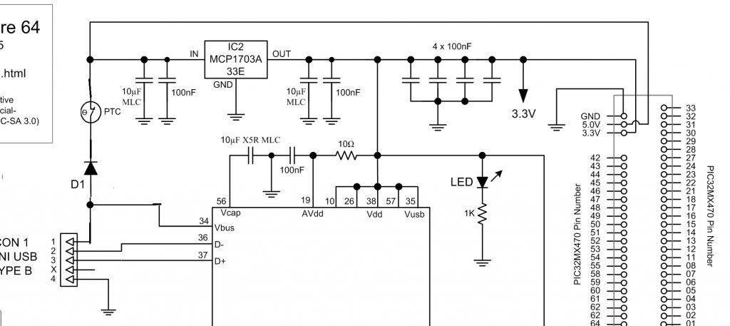
Explore64 1B for others.zip Does this help?  Jim VK7JH MMedit MMBasic Help |
||||
| Mixtel90 Guru Joined: 05/10/2019 Location: United KingdomPosts: 6798 |
Oh, so the 1B is already protected by an invisible D1, :) It's on the schematic but I can't spot it on the PCB pictures. Do I need to clean my glasses? (It only appeared on Version 1C, just in case someone is looking). Edited 2023-09-28 17:10 by Mixtel90 Mick Zilog Inside! nascom.info for Nascom & Gemini Preliminary MMBasic docs & my PCB designs |
||||
TassyJim Guru Joined: 07/08/2011 Location: AustraliaPosts: 6100 |
No, The diode is a mod I did to bring it up to the 1C capability. I should have explained that! Jim VK7JH MMedit MMBasic Help |
||||