|

|
Forum Index : Microcontroller and PC projects : Time offset between two pins
| Page 1 of 3 |
|||||
| Author | Message | ||||
| Frank N. Furter Guru Joined: 28/05/2012 Location: GermanyPosts: 830 |
Hello to all, I would like to use a PicoMite to measure the amount of time between the low/high transition of two pins. So a timer would have to be started when the first pin goes high and stopped again when the second pin also switches from low to high. What is the easiest way to program this? I don't know how to solve this with an interrupt... (It can also happen that the second pin is already High - then it would have to wait until it becomes High again...) To poll the inputs cyclically would be one possibility - with interrupt it would be more accurate? The task is to determine the time offset of the zero crossings of two 50Hz sinusoids, which were previously transformed into square wave voltages by two comparators. Any programming suggestions would be very welcome! THANKS!!! Frank |
||||
| Volhout Guru Joined: 05/03/2018 Location: NetherlandsPosts: 4243 |
What is the accuracy you need ? Of coarse the PIO is the most accurate way, or Peter's CSUB. But if accuracy is not needed to be high (i.e. just to check if a 3 phase syste is left- or right-rotating) then you could do interrupts one interrupt for each zero crossing input pin each interrupt just stores the TIMER into a variable the main level only calculates the difference ... Volhout P.S. with an extra logic gate you can convert the 2 zero crossing signals to a single pulse. Then a single pin could measure pulse width. P.P.S. Peters CSUB Option explicit Option default none ' Interrupt myint 'set up an interrupt that can be triggered by the CSUB ' SetPin gp6,cin,3 'set pin 9 (GP6) to cause a H/W interrupt on both edges ' Dim a%(100) 'array to receive the timestamps Dim b%=100 'maximum number of transitions to receive Dim c%=20000000 'timeout of the CSUB in microseconds ' log a%(),b%,c% 'initialise the logging ' Do :Loop 'loop continuously ' Sub myint 'subroutine that is triggered when the non-blocking CSUB terminates ' local integer i Do While a%(i) 'read all valid data Print i,a%(i) 'print it out Inc i 'increment the loop counter Loop Print "end" Pause 200 End 'terminate the program End Sub ' ' This CSUB logs activity on GP6, each transition of the pin is ' logged to the nearest microsecond. The timestamp is positive for positive ' going transitions and negated for negative going ones ' The parameters are: ' an integer array to hold the timestamps ' an integer with the number of samples to take (the array must be at least this big) ' an integer giving a timeout in microseconds for the CSUB to terminate ' if the number of sample requested is not reached ' when either the timeout occurs or the number of samples is reached the ' CSUB triggers an interrupt to let the Basic program know CSUB LOG 00000041 'check_timer B082B580 4B10AF00 3320681B 4B0F607B 4798681B 681A687B 4299685B D10ED803 D8004290 4B0AE00B 2200681B 4B09601A 2200681B 4B08601A 2201681B 46C0601A B00246BD 46C0BD80 1000038C 100003AC 10000388 100003C8 100003D0 'intprog B085B590 4B22AF00 60FB681B 681B4B20 60BB3310 681B68FB 68BB607B 1E5A681B 601A68BB 681B68BB DC0B2B00 681B4B19 601A2200 681B4B18 601A2200 681B4B17 601A2201 681B4B16 47982009 D0081E03 681B4B14 00024798 6879000B 604B600A 4B10E00C 4798681B 000B0002 42502100 687C4199 000B0002 60636022 681B68FB 001A3308 601A68FB 46BD46C0 BD90B005 1000038C 10000388 100003C8 100003D0 1000032C 100003AC 'main B088B580 60F8AF00 607A60B9 681B4B16 447A4A16 4B16601A 4A16681B 601A447A 681B4B15 4B1461FB 3310681B 4B1261BB 3320681B 68FA617B 601A69FB 681A68BB 69BB685B 4B0D601A 4798681B 000B0002 68086879 18126849 6979414B 604B600A 46BD46C0 BD80B008 100003C8 FFFFFF43 10000388 FFFFFEDD 1000038C 100003AC End CSUB Edited 2023-09-08 22:25 by Volhout PicomiteVGA PETSCII ROBOTS |
||||
| phil99 Guru Joined: 11/02/2018 Location: AustraliaPosts: 2135 |
Untested but may be worth a try. Do Do : loop until pin(1) And pin(2) 'Wait for both to be high Do while pin(1) And pin(2) : loop 'Wait for pin2 to fall if pin(1) And (Not pin(2)) timer = 0 : Do while pin(1) And (Not pin(2)) : loop : T = timer Print "Time between falling edges ";T;"mS" EndIf Loop Edited 2023-09-08 22:36 by phil99 |
||||
| Frank N. Furter Guru Joined: 28/05/2012 Location: GermanyPosts: 830 |
@Volhout: The two curves represent the current and voltage. I need the current/phase offset to see if (and how much) current is being consumed or generated. I am not yet clear about the required resolution. I think 0.1 to 0.5 milliseconds should be enough... Does this CSUB really work on a PicoMite? That's a good idea! @phill99: Your solution looks quite interesting too! THANKS! Frank |
||||
| Volhout Guru Joined: 05/03/2018 Location: NetherlandsPosts: 4243 |
Hi frank, The csub may need re-compiling for the latest firmware. If I read correct you have analog voltage and analog current from the adc. Assuming you have multiple samples per 50hz sine wave. Why not multiply the associated samples? Gives you true watts. Rms the voltage Rms the current Multiply these gives VA Cos phi is watt/VA This does not give you the actual inductive/capacitive value, for this you would need an additional step. But you do not need any additional hardware. Just the data you already have in the memory. Volhout P.S. you can find positive/negative angle by by finding the first zero crossing in voltage array, and the first in current array. That will tell you pos or neg. angle. Edited 2023-09-09 04:09 by Volhout PicomiteVGA PETSCII ROBOTS |
||||
| Bernie3D Newbie Joined: 02/08/2023 Location: United StatesPosts: 19 |
@Volhout I can confirm that CSUB fails on Picomite v50707b18 and beyond. It was possibly the update on SDK v1.5, which occurred on that release. I like that CSUB for decoding a pulse trains like Manchester code, which are used in protocols like LTC (Linear TimeCode). It would be a nice Function, something like PULSIN. |
||||
| Frank N. Furter Guru Joined: 28/05/2012 Location: GermanyPosts: 830 |
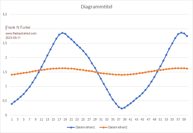
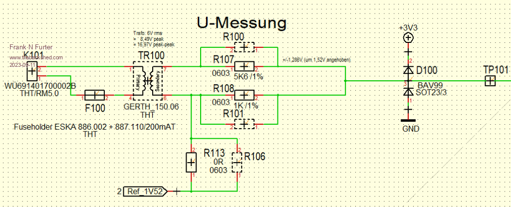
Hi Volhout, My problem is that the voltage curve is distorted, because I can tap the voltage only after a transformer. Don't you think it would be better to detect the zero crossing and then superimpose an ideal sine wave over it? This is what my measurement currently looks like:  Blue is the mains voltage (after the transformer) and raised into the positive range (1V52), red is the current waveform (here from a 1800W hairdryer). How would you evaluate these measurement results now???  THANKS! Frank Edited 2023-09-11 17:20 by Frank N. Furter |
||||
| Mixtel90 Guru Joined: 05/10/2019 Location: United KingdomPosts: 6798 |
You can never be sure of the wave shape from the mains supply. It varies with the load at any one time as well as with whatever transformers are feeding your site. It's always distorted to some extent. Because of power factor there is rarely any relation between load voltage and load current unless the load is purely resistance heating (no motors). Basically, if you want reasonable accuracy work with either voltage at the load terminals or current into the load but not both unless you really *have* to calculate power into the load. Try to avoid that if you can, for that way madness lies. :) The "proper" way to do it is to use a True Watts Transducer. They are a current transformer and voltage monitor combined and produce a control voltage or current that is proportional to the load Watts, no matter what the power factor is. They cost rather a lot though, being industrial gear. Mick Zilog Inside! nascom.info for Nascom & Gemini Preliminary MMBasic docs & my PCB designs |
||||
| phil99 Guru Joined: 11/02/2018 Location: AustraliaPosts: 2135 |
This version of CSub LOG may work. CSub LOG update The mains waveform shown above is too distorted. Mains distortion rarely exceeds 5%. Put a resistive load on the transformer output, 10% of it's rated power will do then see if it looks better. Edited 2023-09-11 18:39 by phil99 |
||||
| Frank N. Furter Guru Joined: 28/05/2012 Location: GermanyPosts: 830 |
@Mixtel90: Oh, I think I can be sure of that! Nothing more than the measuring unit is connected to the transformer - i.e. without any additional load.  I got the idea from here! Frank |
||||
| Volhout Guru Joined: 05/03/2018 Location: NetherlandsPosts: 4243 |
I also started out with using a transformer to isolate mains voltage. But the transformer showed similar distortion as yours. I tried (resistive) loading the transformer, but until the load was really close the the transformer rating (several Watt) it remained distorted, and worse, it showed phase lag. I settled on this circuit mains analyzer The 10meg resistors are high voltage resistors. They isolate mains voltage from your picomite. 10 meg is sufficiently high to have minimal leakage current (it is safe to touch). Note that I used 4 resistor 75k (you can also use 68k) so they are best matched. Preferably 1% or better parts, preferably also get 10 meg 1% parts. Volhout Edited 2023-09-11 19:17 by Volhout PicomiteVGA PETSCII ROBOTS |
||||
TassyJim Guru Joined: 07/08/2011 Location: AustraliaPosts: 6099 |
I get reasonable waveforms using a small toriodal core transformer lightly loaded. With your two waveforms. subtract the mean to get them centred about zero. multiply the two arrays element by element to get instantaneous power. the mean will be positive or negative depending on direction. I will try and put up some code and resulting graphs tomorrow some time. I am presently developing a power monitor so the timing is fortunate. Jim VK7JH MMedit MMBasic Help |
||||
| Mixtel90 Guru Joined: 05/10/2019 Location: United KingdomPosts: 6798 |
All VTs introduce a measure of phase error simply because the windings are inductive and there is capacitive coupling between them. You can reduce the errors by paying more, strangely enough. :) Mick Zilog Inside! nascom.info for Nascom & Gemini Preliminary MMBasic docs & my PCB designs |
||||
| Frank N. Furter Guru Joined: 28/05/2012 Location: GermanyPosts: 830 |
@Volhout: Your solution looks good - unfortunately I need mandatory galvanic isolation!  @TassyJim: Can you tell me which transformer you used for this? I would be very interested in the exact type... @Mixtel90: With a constant load, the phase shift should also be constant and can therefore be calculated out... I have now tried reducing the load on my transformer - the curve now looks better. However, the amplitude (also because of the downstream low-pass) is now much too low and everything would have to be adjusted again...  Frank |
||||
| Volhout Guru Joined: 05/03/2018 Location: NetherlandsPosts: 4243 |
That is okay, since it is a 1x execsize. As long as it represents the input waveform that should be fine. Maybe it is not usefull, but if you want some reading: energy meter.zip This is how they achieve a relatively good and simple energy meter using onboard ADC's inside a microcontroller. But they hard connect the micro to the Neutral of the mains network, and opto isolate the output. It was nice reading though. And yes, you are correct , the high impedance resistors are no galvanic isolation. Did you know these resistors where in every switchmode power supply up to 10 years ago the meet the requirement that after pulling the power plug, the pins should be discharged withing 2 seconds. So Y-capacitors where discharged using these resistors. Volhout Edited 2023-09-11 21:29 by Volhout PicomiteVGA PETSCII ROBOTS |
||||
| matherp Guru Joined: 11/12/2012 Location: United KingdomPosts: 9122 |
What about using analogue opto isolators. I've used HCNR201 in the past and they work well |
||||
| Frank N. Furter Guru Joined: 28/05/2012 Location: GermanyPosts: 830 |
@Volhout: Thank you for your interesting document. @matherp: How would you set that up then? Frank |
||||
| matherp Guru Joined: 11/12/2012 Location: United KingdomPosts: 9122 |
On the non-isolated side scale the incoming mains to suit the opto Then pass that through the opto and use the adc on the isolated side to detect the zero |
||||
| Volhout Guru Joined: 05/03/2018 Location: NetherlandsPosts: 4243 |
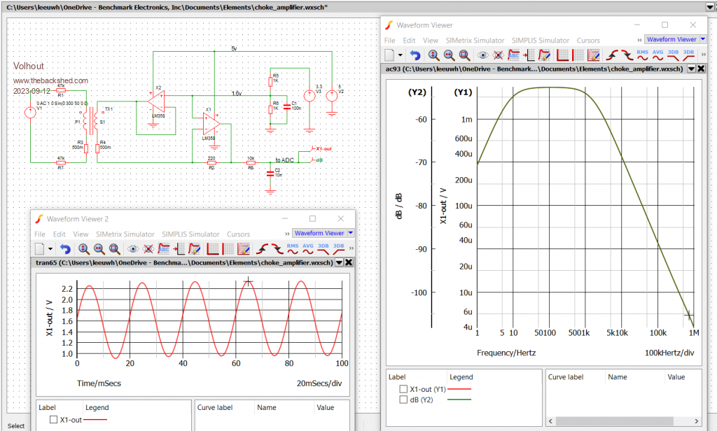
@Jim, Frank, I was amazed to see that you can use a common mode choke (ferrite material, not iron core) to measure mains voltage. The trick is to run it really low current, since it represents a really low impedance, and saturates easy. And terminate it in a virtual ground or other low impedance. To be usefull you need a common mode choke with a lot of turns on it. using common mode choke I just tried it with a 33mH commercial choke, and it actually works. When you drive the common mode choke core too hard, it shows similar distortion as Frank's waveform. Maybe this is something Frank can try as well. Just put a lower voltage at the input of the transformer (33k/33k voltage divider so you have 115V to drive the transformer). Never too old to learn... Regards, Volhout Edited 2023-09-11 22:54 by Volhout PicomiteVGA PETSCII ROBOTS |
||||
| Volhout Guru Joined: 05/03/2018 Location: NetherlandsPosts: 4243 |
Simulation shows that something like this should work to measure mains voltage. I will try to prototype (build actual circuit) tomorrow.  PicomiteVGA PETSCII ROBOTS |
||||
| Page 1 of 3 |
|||||