|

|
Forum Index : Microcontroller and PC projects : Breadboard friendly module.
| Author | Message | ||||
| Bernie3D Newbie Joined: 02/08/2023 Location: United StatesPosts: 19 |
One thing I like about the Picomite (besides the amazing work Peter has put into this thing) is how small and breadboard friendly it is. Since I'm still new to this, please forgive my ignorance. I started on the Picomite, but when there was a recent post on a new version of the Armmite F4, I ordered a couple of STM32F407VET6 boards to play with. I was impressed by the improved performance over the Picomite, so I looked around for a breadboard friendly development board that would hopefully run F4 code. I dug a bit deeper and discovered the F407 and F405 share the same datasheet and ref manual, so I bought a couple of Adafruit STMF405 Feather Express boards. They use 64 pin chips, which are missing PortE and most of PortD. I didn't need the FSMC connector,IR, Kbd-Data, etc. I was happy the Ports used for the included SDCard (on SDIO) and 2MB serial flash were identical, so I thought this module would work. Unfortunately it didn't, although I did see the copyright banner on TeraTerm on boot-up, and a command prompt >. I assume it's Key0,1 missing which is causing a problem, possibly causing a switchover to serial console. I am interested in USB console only. If there is anyone that may give any advice on a solution, I would much appreciate it, or even suggest another breadboard friendly development board on another Mite. Thanks! |
||||
| lizby Guru Joined: 17/05/2016 Location: United StatesPosts: 3150 |
How many pins do you need, and what hardware interfaces? The VGT6 version here works to a degree (or at least it did 3 years ago), but with issues, and you could just use 2 of the 4 rows, though you could be missing some features which require pins which are not on the rows you pick. There's a thread about it here. I'm not sure anyone got very far with it. I got it working with an ILI9341, SD card, RTC, LEDs, DS18B20, but have a note that I2C failed. I did not pursue it. You would be breaking trail if you tried it, and USB console might or might not work. If you got as far as a prompt, perhaps Garry would have an interest in looking at the F405 Feather, but it's a pretty pricy board. There are F4 "hats" and prototyping boards, including one which breaks out the pins to a pi-type 2x20 pinout: Armmite F4 Hardware The older MMBasic boards which are breadboard-friendly don't match up well with the PicoMite on either price or capability. ~ Edited 2023-09-05 09:55 by lizby PicoMite, Armmite F4, SensorKits, MMBasic Hardware, Games, etc. on fruitoftheshed |
||||
| Bernie3D Newbie Joined: 02/08/2023 Location: United StatesPosts: 19 |
@lizby Thanks for the response. Most of my projects don't need too many pins. Typically a UART or two, a SPI bus, a USB port to occasionally connect to a PC, and a SD Card. Sometimes a SPI display for status as relatively slow text. I typically talk to cinema cameras, and related interface boxes using serial protocols, which isn't too fast. I do need it to be as small as possible, even in prototype form. Maybe Garry can suggest something. I don't want to burden him too much as he likely is busy getting up to speed after taking on the F4 development. Bernie |
||||
| disco4now Guru Joined: 18/12/2014 Location: AustraliaPosts: 897 |
Hi Bernie, The STM32F407VGT6 Lizby points to should work OK. I have one and just run it up to check. It is essentially to same as the STM32F407VET6 MINI (that is what I called it in the manual) but has an extra 512K of flash which MMBasic doesn't know about. Its fully documented in the manual. The main difference is the CS for the flash is on pin 77 in lieu of 35 and there is not a dedicated FSMC connector. The Adafruit STMF405 Feather Express looks interesting, though a bit expensive. I will order one and see if I can make it work. One thing that could be stopping it is that MMBasic by default configures a parallel display using the FSMC pins, which aren't there, so that would be one of the first things it discovers.(this is done so that anyone buying the F4 board and the matching LCD Panel has something that just works out of the box) As the STMF405 seems to have the 1Meg of flash the same as the VGT version in future in might be possible to do a binary that makes use of the 1Meg flash and be smart enough to handle both the 64pin and 100 pin versions. The current F4 software that fits into 512K of flash is compiled for smallest size and has near no room left. Gerry. Latest F4 Latest H7 |
||||
| Bernie3D Newbie Joined: 02/08/2023 Location: United StatesPosts: 19 |
@disco4now Nice name  Thanks for taking on the F4 project, updating it, and adding to the manual where Peter left off. Reading your contributions in your posts it seems you are amply knowledgeable to take on this project. I will check out the VGT6 board. Thanks for checking out the Adafruit board. Hopefully you can find a easy way to make it work, even within the existing 512k limit. Thanks for all, Bernie |
||||
| lizby Guru Joined: 17/05/2016 Location: United StatesPosts: 3150 |
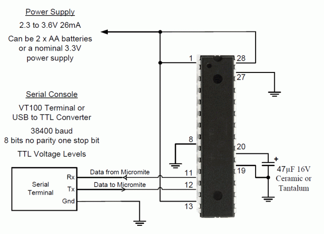
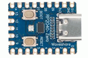
If you want the smallest possible on a breadboard, it will be hard to beat the original MicroMite--if you can find the chip:  The only component you need is the 47uF 16V capacitor (plus your serial connection). Flashing the chip with MMBasic is an issue, though--nothing beats the Picomite for ease of flashing. If you want a smaller PicoMite, check out the breadboard-friendly RP2040 module  PicoMite, Armmite F4, SensorKits, MMBasic Hardware, Games, etc. on fruitoftheshed |
||||
| Mixtel90 Guru Joined: 05/10/2019 Location: United KingdomPosts: 6798 |
That little board (the RP2040 Zero) is great for breadboarding, but only if you want the pins on the two long sides. 9-13 don't work in a breadboard unless you put a separate header on them. Having said that, it's a great little board and is probably cheaper than the Micromite! Board space is actually smaller if you were going to use some sort of regulator, capacitors and some components to connect a Micromite to its console. Mick Zilog Inside! nascom.info for Nascom & Gemini Preliminary MMBasic docs & my PCB designs |
||||
| Bernie3D Newbie Joined: 02/08/2023 Location: United StatesPosts: 19 |
@lizby Thanks for the info on the smallest packages. I certainly can use these in some future projects. I like to start on a breadboard, because when I have an oops-moment I can plug in another one, and continue before I forget what I was doing. @Mixtel90 Thanks! I will check the pinout for the interfaces I need. Right now I'm looking for something small that has an SDCard support, with a decent performance. Maybe I will also look at the MM+/Explorer64 board. I also need to get into the MMX in 64 pin version, which seems to have some amazing specs. It seems I can overclock the Picomite for better performance, although I am typically uncomfortable in doing this. It feels like driving my car at 30000RPM. @disco4now I forgot to mention on the Adafruit module (I'm hoping for) that I got the copyright banner and command prompt on TeraTerm on USB, but no further response even though Windows maintained the CDC in Device Manager. I also had to drop in a 8MHz crystal to match the Armmite F4. Thanks all for your responses. It's a breath of fresh air in these days of limited tech-support. |
||||
| Mixtel90 Guru Joined: 05/10/2019 Location: United KingdomPosts: 6798 |
SD card support is built into MMBasic now, you just need to sort out the hardware. :) The combination of a RP2040 Zero and a small breakout module from ebay / AliExpress would give you a similar board area to one of the more expensive RP2040 modules with built-in uSD socket, albeit with less IO. Overclocking the RP2040 appears to have no detrimental effect whatsoever. The core temperature hardly rises. Edited 2023-09-06 17:04 by Mixtel90 Mick Zilog Inside! nascom.info for Nascom & Gemini Preliminary MMBasic docs & my PCB designs |
||||
| lizby Guru Joined: 17/05/2016 Location: United StatesPosts: 3150 |
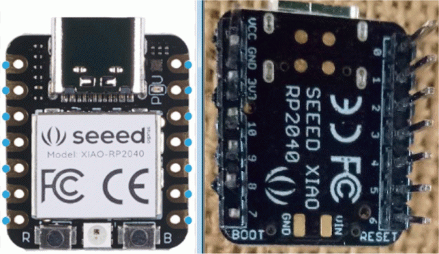
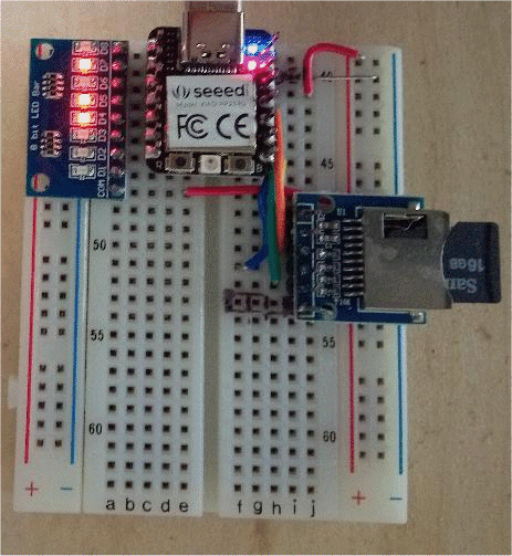
I've done lots of breadboards, but maybe none in the past year or perhaps two. So this was a challenge. The RP2040 mentioned above is superior, but I happened to have a couple of the 14-pin Seeed RP2040 modules.  It was not trivial figuring out the pins from the diagrams and pin numbers on the PCB--they didn't correspond to the Pico pins. After loading MMBasic, I did it by brute force--SETPIN, n,DOUT, then see if I could toggle it. The right-side pins (top view, USB connector up) are (from the bottom up) 2,4,6,5,3v3,0V,5V; the left side pins are 1,10,9,44,31,32,34.  I used a little SD card module (which apparently some have had trouble with, but I haven't) and these options: OPTION SYSTEM SPI 4,5,6 OPTION SDCARD 2. I could successfully examine both the A: drive and the B: drive, and save to the B: drive: PicoMite MMBasic Version 5.07.08b15 Copyright 2011-2023 Geoff Graham Copyright 2016-2023 Peter Mather > files A:/ <DIR> . <DIR> .. 00:00 01-01-2000 4 bootcount 00:37 01-01-2000 292 t1.bas 00:01 01-01-2000 283 t2.bas 2 directories, 3 files, 704512 bytes free > files "B:" B:/ 0 directories, 0 files > b: > files B:/ 0 directories, 0 files > save "test_leds.bas" > files B:/ 00:01 01-01-2000 283 test_leds.bas 0 directories, 1 file I ran this program to randomly turn off and on the LEDs on an 8-LED common anode module (so negative logic--0=on). Dim integer i,j,k,npins=7,p(6)=(1,10,9,44,31,32,34) For i=0 To npins-1 SetPin p(i),dout Pin(p(i))=1 ' negative logic for this common anode 8-led module Next i Do While 1 j=Int(Rnd(1)*2) ' 0 or 1 i=Int(Rnd(1)*npins) ' 0 through npins Pause 500 Pin(p(i))=j Loop (I have to ask--do you really need an SD card, considering that MMBasic for the RP2040/Pico has the small file system built into flash?) ~ Edited 2023-09-07 02:33 by lizby PicoMite, Armmite F4, SensorKits, MMBasic Hardware, Games, etc. on fruitoftheshed |
||||
| Mixtel90 Guru Joined: 05/10/2019 Location: United KingdomPosts: 6798 |
Fairly small to have a micro SD. I ran out of space to write things on it. :) You can't surface mount the Zero, so the resistor and SMD cap are underneath it, The uSD socket is on the back of the board. The assembly is still breadboard friendly if you ignore the fact that GP9 isn't available. Mick Zilog Inside! nascom.info for Nascom & Gemini Preliminary MMBasic docs & my PCB designs |
||||
| Bernie3D Newbie Joined: 02/08/2023 Location: United StatesPosts: 19 |
@lizby Thanks! That Seeed module seems to be breadboard-friendly and small. I like that the RP2040 breaks out the UARTs/SPIs/I2Cs all over the place, allowing the Pico to be chopped in half, and still have all those interfaces available. I just ordered a 3-pack of Zeros from Waveshare. I have had great success with the Waveshare RP2040-Plus with 16MB flash (which I think Peter suggested a while back). It's great to have that Flash File system. While 16MB is ample for most projects, I do need an SDCard for other projects, such as logging time-stamped metadata for use in movie post-production for special effects, and for "MoCo" (Motion Control) projects. @Mixel90 That's about as small as you can get, with a sandwiched SDCard board. I am curious as to what starts to break when you overclock. I assume the RP2040 itself is more consistent and the QSPI Flash would vary more by manufacturer. I'm sure Peter is auto ranging the various clocks to be within a safe area, when an overclock frequency is chosen. |
||||
| Mixtel90 Guru Joined: 05/10/2019 Location: United KingdomPosts: 6798 |
I have my own theories about overclocking the RP2040. I've done precisely zero research on this. :) I suspect that during the design stage an arbitrary figure was chosen for the clock speed to make things easy and economic. The dual ARM core used is rated at 133MHz, which was probably the best compromise. Remember that 133MHz is the speed that ARM will guarantee their customers with both cores flat out under all conditions. There's no reason to think it's a hard limit. The RP2040 is very small and very "modular" and not all of the die is likely to be under thermal stress at any one time. That allows heat to be conducted away very easily, making it a thermally efficient chip. Ultimately it's thermal stress that limits the characteristics of a chip, only serious heat can "break" a chip. This probably wasn't designed in, as such, and is probably a happy accident. :) That's the end of my harebrained ideas. :) What we know in practice is that the PicoMite will run continually at 384MHz. There is a slight increase in core temperature above ambient, as detected using the built-in sensor, but it's well within even the low end of the expected temperature band. There is no reason to think that this is putting any stress on the chip whatsoever. I suppose, if it was possible to test every single combination of every bit on every pathway in the chip you might eventually discover a thermal weakness at some point, but that isn't currently possible within the lifetime of a universe. Mick Zilog Inside! nascom.info for Nascom & Gemini Preliminary MMBasic docs & my PCB designs |
||||