|

|
Forum Index : Microcontroller and PC projects : Bought a 16 MB Ram pico but
| Page 1 of 2 |
|||||
| Author | Message | ||||
| Plasmamac Guru Joined: 31/01/2019 Location: GermanyPosts: 554 |
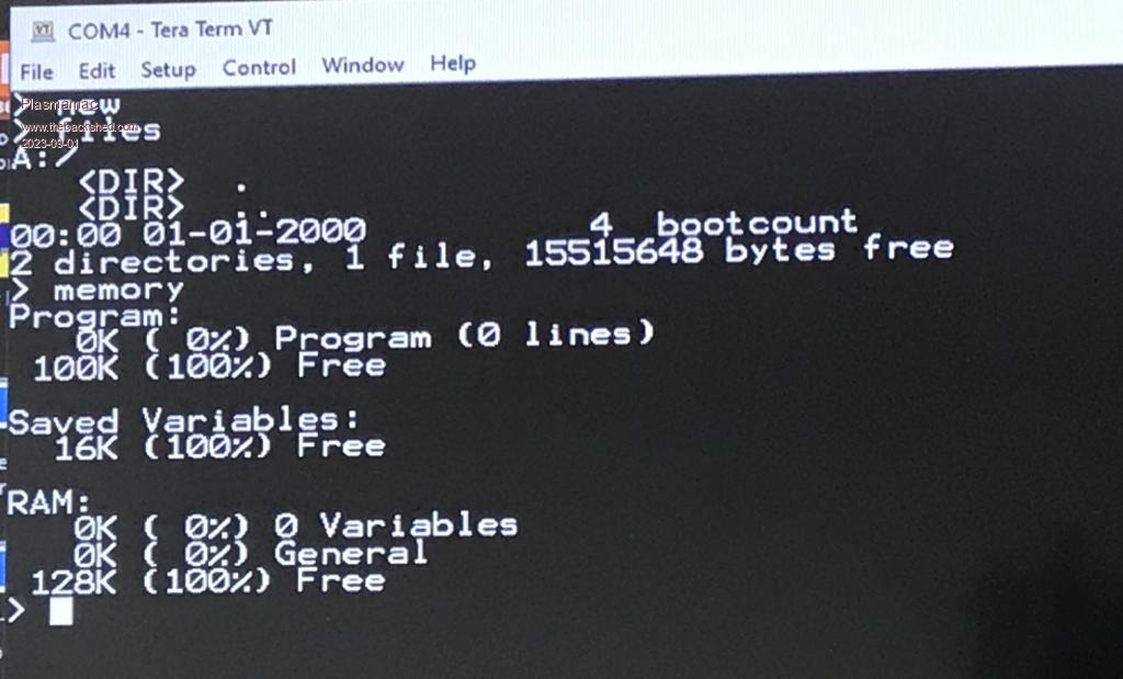
It shows the same memory Size as normal. Am i wrong ?  Plasma |
||||
| matherp Guru Joined: 11/12/2012 Location: United KingdomPosts: 9126 |
What does the FILES command show |
||||
| Plasmamac Guru Joined: 31/01/2019 Location: GermanyPosts: 554 |
Ahh looks better  Plasma |
||||
| Mixtel90 Guru Joined: 05/10/2019 Location: United KingdomPosts: 6798 |
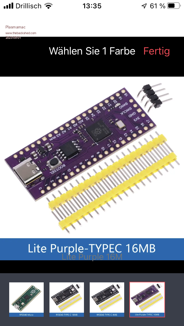
Be careful with that version, it's not PicoMite pin-compatible. Mick Zilog Inside! nascom.info for Nascom & Gemini Preliminary MMBasic docs & my PCB designs |
||||
| Plasmamac Guru Joined: 31/01/2019 Location: GermanyPosts: 554 |
oh no (lemmings sound). thx Matherp and Mixtel Plasma |
||||
| Mixtel90 Guru Joined: 05/10/2019 Location: United KingdomPosts: 6798 |
Ah, but you gain extra flash storage, USB-C and extra I/O so it's not all bad. :) I'll be interested to see how far it will overclock. The YD-RP2040 locks up at a bit over 200MHz. Mick Zilog Inside! nascom.info for Nascom & Gemini Preliminary MMBasic docs & my PCB designs |
||||
| phil99 Guru Joined: 11/02/2018 Location: AustraliaPosts: 2136 |
The one I have runs fine at 378MHz though the chip temp. is a few degrees higher than the others. |
||||
| JohnS Guru Joined: 18/11/2011 Location: United KingdomPosts: 3802 |
Can we change the thread title? It's 16MB flash not RAM... John |
||||
| Plasmamac Guru Joined: 31/01/2019 Location: GermanyPosts: 554 |
378 MHZ run fine , no temperature test atm Plasma |
||||
| Plasmamac Guru Joined: 31/01/2019 Location: GermanyPosts: 554 |
I can’t change the threadtitle. Plasma |
||||
| stanleyella Guru Joined: 25/06/2022 Location: United KingdomPosts: 2129 |
I got a "normal" rpi2040 and mem says RAM: 0K ( 0%) 0 Variables 0K ( 0%) General 152K (100%) Free The 16MB ram rpi pico is 128K ??? |
||||
| Mixtel90 Guru Joined: 05/10/2019 Location: United KingdomPosts: 6798 |
The extra flash (not RAM - that's the same) is only used for file storage, Stan. You'll only see it with FILES. Mick Zilog Inside! nascom.info for Nascom & Gemini Preliminary MMBasic docs & my PCB designs |
||||
| stanleyella Guru Joined: 25/06/2022 Location: United KingdomPosts: 2129 |
Mick- like github,easy not > files A:/ <DIR> . <DIR> .. 00:00 01-01-2000 4 bootcount 2 directories, 1 file, 712704 bytes free > memory Program: 1K ( 0%) Program (25 lines) 123K (100%) Free Saved Variables: 16K (100%) Free RAM: 0K ( 0%) 0 Variables 0K ( 0%) General 152K (100%) Free > not a clue |
||||
| JohnS Guru Joined: 18/11/2011 Location: United KingdomPosts: 3802 |
With 16MB flash I expected A: to have more free space. John |
||||
| Mixtel90 Guru Joined: 05/10/2019 Location: United KingdomPosts: 6798 |
I don't know which versions of MMBasic are on both of them. The amount of free flash will vary. Doesn't Free RAM indicate how much is free with a program loaded? It's not something I've ever worried about. :) Mick Zilog Inside! nascom.info for Nascom & Gemini Preliminary MMBasic docs & my PCB designs |
||||
TassyJim Guru Joined: 07/08/2011 Location: AustraliaPosts: 6100 |
The 'black' version has a pinout that is 'almost' the same as the pico. My black boards need to be kept below 200MHz but that is not too bad. The extra disk space negates the need for a SDcard. Edit: I just tried a black board at 378MHz on the latest firmware and it looks OK. I will leave it running for a few hours and see. Jim Edited 2023-09-02 08:19 by TassyJim VK7JH MMedit MMBasic Help |
||||
| Pluto Guru Joined: 09/06/2017 Location: FinlandPosts: 359 |
Regarding the black RP2040 modules: -Up to now I have been very pleased with the black models YD-RP2040 2022-V1.3 (with 16MB and a RGB-led on board). -Now I am not so pleased anymore. I have over the last days followed the oscilloscope developments and tested various programs posted. Nothing seemed to work as it should have. Swithed over to a genuine green module and everything worked as intended! Have anybody else had truble with ADC on the black modules? Or is it just a coincidence that both of the black modules happened to have problems? Are the ADC inputs wired differently on green and black modules? (At least I could not see any differences) option list PicoMite MMBasic Version 5.07.08b15 OPTION SYSTEM SPI GP18,GP19,GP16 OPTION LCDPANEL ILI9341, LANDSCAPE,GP15,GP14,GP13 OPTION TOUCH GP12,GP11 GUI CALIBRATE 0, 3844, 3970, -837, -639 Pluto |
||||
| stanleyella Guru Joined: 25/06/2022 Location: United KingdomPosts: 2129 |
Nobody worry's about ram or code space. There's plenty. right? Just assume there's enough and it's happy days. sarcy mode off |
||||
| stanleyella Guru Joined: 25/06/2022 Location: United KingdomPosts: 2129 |
Nobody worry's about ram or code space. There's plenty. right? Just assume there's enough and it's happy days. sarcy mode off bye bye rasbpery pi drove my gp to the limit and my pi got fried |
||||
| Mixtel90 Guru Joined: 05/10/2019 Location: United KingdomPosts: 6798 |
What problems are you seeing? Remember that the ADC command will still require ADC0, which you can't change. I've not used the ADC inputs on the YD-2040 yet. According to the circuit they are connected similarly, with the exception that ADC3 is also on a pin. There is better reference voltage smoothing on the Pico. You can add this by connecting a capacitor to the VREF and GND pads. You could put a header here so that a capacitor and voltage ref could be added at some point. Note that the reduced smoothing may not be a problem as the 3V3 regulator is linear rather than switching. ======================================= EDIT: I've found the problem. As the board comes the ADC reference is disconnected so those inputs can't be used as analogue! There are two round pads, marked VREF and GND. The VREF pad goes to the RP2040 input and has a 100nF capacitor to GND. The simplest way is to put a header in the VREF and GND pads. You can then connect a 220R resistor from 3V3 to VREF and a 2.2uF to 10uF capacitor from VREF to GND. If you want the resistor to go on the module, then there is a solder-blob link further to the left, also marked VREF. The left side goes to 3V3 and the right to the VREF pad mentioned previously. . Edited 2023-09-06 06:57 by Mixtel90 Mick Zilog Inside! nascom.info for Nascom & Gemini Preliminary MMBasic docs & my PCB designs |
||||
| Page 1 of 2 |
|||||