|

|
Forum Index : Microcontroller and PC projects : Quick CT question about DC current....
| Author | Message | ||||
Grogster Admin Group Joined: 31/12/2012 Location: New ZealandPosts: 9308 |
Hi all.  We all know of the CT's you can use to measure AC current, but can I just run an idea past the members please? I want to detect DC current using one of these. Reading around on the net, I have seen a few posts on various forums that suggest you can use a CT to measure DC current, if you shunt the CT with a resistor, but I have no idea what value I should use. The modules I was going to play with are these ones here. I am dubious about a plain CT with a resistor shunt working for DC current - perhaps some other members here can comment on that. I would have expected a plain CT to only work for AC current.... The other modules I am looking at are more expensive, but use a hall-effect device as the sensor, and those I expect would work well for DC current. Correct? Here are the hall-effect modules I was thinking of using. But just a little confused as to which one. I THINK the hall-effect one is the one I need to go for, but if I can use the cheaper one, then so much the better. Any advise or suggestions appreciated. Only need to detect a few amps of current and switch a relay, which is why I like the first module so much - it has everything I want including the relay, that the 2nd module does not have. However, it it not like it is going to be very painful to connect a suitable relay to the 2nd module, but I just liked the fully self-contained first module. But I don't think that one will work for DC current. Smoke makes things work. When the smoke gets out, it stops! |
||||
| phil99 Guru Joined: 11/02/2018 Location: AustraliaPosts: 2136 |
Yes, CTs can't detect DC, though if there is ripple on the DC they can measure that component. For DC the options are a hall-effect device or shunt resistor and differential amplifier to drive the relay. Depending on the accuracy you require the Dif. Amp. could be a single transistor. |
||||
Grogster Admin Group Joined: 31/12/2012 Location: New ZealandPosts: 9308 |
Excellent, thanks Phil.  I'll get the hall type then. Will just have to add my own relay on the back of it.  Smoke makes things work. When the smoke gets out, it stops! |
||||
| Volhout Guru Joined: 05/03/2018 Location: NetherlandsPosts: 4247 |
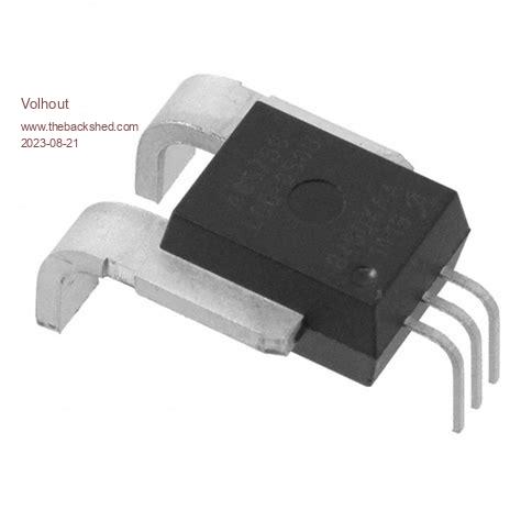
The hall type is plenty avalable in PCB (chip) form up to 100A.  Edited 2023-08-21 15:23 by Volhout PicomiteVGA PETSCII ROBOTS |
||||
| Mixtel90 Guru Joined: 05/10/2019 Location: United KingdomPosts: 6798 |
An AC current transformer will merely saturate on DC and you'll get nothing out of it. There are devices that look like small CTs that work on either AC or DC. They use a Hall Effect sensor and the output is normally 0V, swinging positive or negative around that to follow the waveform. These things even have a hole through them for the current carrying conductor. Much, much cheaper is a simple shunt and an op amp. :) Mick Zilog Inside! nascom.info for Nascom & Gemini Preliminary MMBasic docs & my PCB designs |
||||
Grogster Admin Group Joined: 31/12/2012 Location: New ZealandPosts: 9308 |
That's a grunty looking thing!  Smoke makes things work. When the smoke gets out, it stops! |
||||
Grogster Admin Group Joined: 31/12/2012 Location: New ZealandPosts: 9308 |
@ Mick - feel free to post examples.  I need to measure BOTH high-side current AND low-side current(depending on situation), which is why I was looking at the CT/HALL type devices, which, I figure, can be installed in either the supply or load side, and still work. ELECTRICALLY interrupting the load carrying conductor, is not possible. The control electronics(f-ing car computer) will have a fit. The load as measured by the computer, will go into a fault condition, if you put any extra load on the circuit, or introduce any kind of serious series resistance - it will see that as a load fault, and trip an error condition. That's why I am going down this path, as CT/HALL sensors WON'T upset the original load current as far as the computer is concerned - we are just sniffing for the value of the current that is going past.  Smoke makes things work. When the smoke gets out, it stops! |
||||
| Mixtel90 Guru Joined: 05/10/2019 Location: United KingdomPosts: 6798 |
The things I was thinking of are made by a company called LEM. They do all sorts of sizes. Actually, on the first page that you link to, they look like the blue one in the bottom right hand corner. Linky One of their ranges is virtually identical. You see the supply voltage is 5V and the output is +/-2V5 ? With 5V supply the output will sit at 2V5 with no current through it. Remember, a 6A device will sense +/-6A DC not 6A RMS. Edited 2023-08-21 17:56 by Mixtel90 Mick Zilog Inside! nascom.info for Nascom & Gemini Preliminary MMBasic docs & my PCB designs |
||||
| CaptainBoing Guru Joined: 07/09/2016 Location: United KingdomPosts: 2076 |
Ayup Grogster. I like to keep things simple and I used a few of these in my time ACS712 and the (datasheet) They provide an analogue output with 0A at half VCC (so they mesure negative and positive currents) I then use an AIN pin to measure the voltage and the Map() function to give me current. > ? map(2.51,0,5,-10,10) '2.51V in the range 0 to 5V maps onto the range -10A to +10A 0.04 '(40mA) > ? map(2.49,0,5,-10,10) '2.49V -0.04 > the device is available in 5A, 20A & 30A flavours. The current sense in my heated build plate plate uses a 5A device hth Edited 2023-08-21 19:38 by CaptainBoing |
||||
| amigawizard Regular Member Joined: 15/08/2023 Location: AustraliaPosts: 43 |
@Grogster jaycar have this $11 oz CAT.NO: XC4610 https://www.jaycar.com.au/medias/sys_master/images/images/10009289293854/XC4610-arduino-compatible-30a-current-sensor-moduleImageMain-515.jpg Wayne ! |
||||
| Volhout Guru Joined: 05/03/2018 Location: NetherlandsPosts: 4247 |
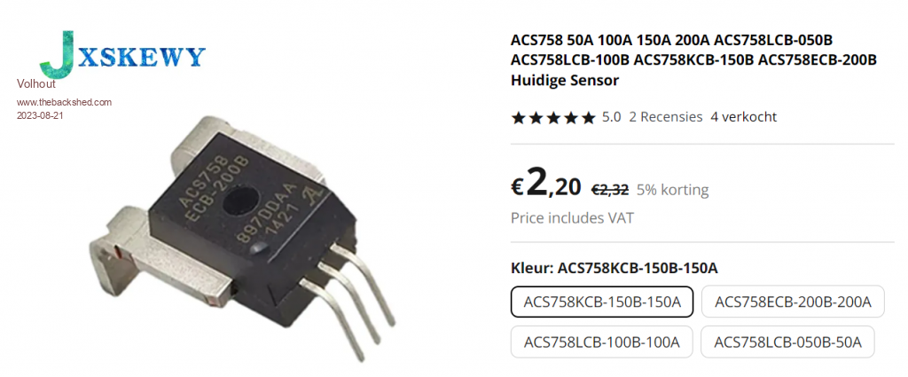
If you make a PCB anyway, this is cheaper...  PicomiteVGA PETSCII ROBOTS |
||||
| lizby Guru Joined: 17/05/2016 Location: United StatesPosts: 3150 |
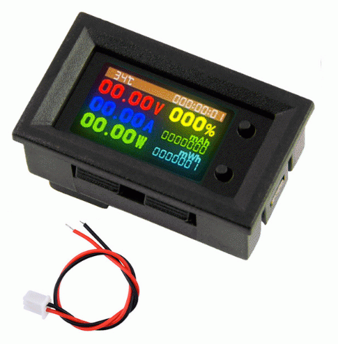
I have found this to be a great little device: VoltAmmeter display .  Now if there was just a convenient way to query it to get a reading via serial. PicoMite, Armmite F4, SensorKits, MMBasic Hardware, Games, etc. on fruitoftheshed |
||||
| Mixtel90 Guru Joined: 05/10/2019 Location: United KingdomPosts: 6798 |
Note that Grogster wants to be able to measure both high side and low side current. I'm not sure if there'll even be a common GND line as he's measuring current on vehicle circuits that are already being current monitored elsewhere. Mick Zilog Inside! nascom.info for Nascom & Gemini Preliminary MMBasic docs & my PCB designs |
||||
| Volhout Guru Joined: 05/03/2018 Location: NetherlandsPosts: 4247 |
The ACS758 series had build in galvanic isolation, so it can directly be used to measure high side. In the TBS forum on electronics it is used to measure inside solar systems and high power convertors. Volhout PicomiteVGA PETSCII ROBOTS |
||||
| Glen0 Regular Member Joined: 12/10/2014 Location: New ZealandPosts: 86 |
I was going to suggest you consider the LEM CASR range of fluxgate type sensors (they have an integrated 2.5V reference), but the Winson device you have found looks quite nice. I suppose you still need to use a differential amp to give a 0V - 3.3V output if you want full resolution. I will have to try one of these. Let us know how you get on. |
||||
Grogster Admin Group Joined: 31/12/2012 Location: New ZealandPosts: 9308 |
Thanks for all the suggestions and links, chums.  Gives me some alternatives to think about. Smoke makes things work. When the smoke gets out, it stops! |
||||
| Volhout Guru Joined: 05/03/2018 Location: NetherlandsPosts: 4247 |
It is important to understand why G. wants to measure both high side as well as low side. If he needs to know the difference, so detect there is DC leaking to earth (i.e. charging an electrical vehicle) then you need to measure differential in one coil/sensor. Charging vehicles goes with 16A plus. The safety limit for DC leak is set to 6mA DC (internatioal standard). Calculating leak from Ihigh and Ilow requiers very high resolution (and accuracy) measurements. 12bit is not enough. And the sensors need to be very high linearity and accuracy. So the trick could be to use a toroid (with a hole in it) sensor, and run both (high and low) wires through it. The difference in current will then be sensed with the HALL element, giving you better resolution for ground leak. A second sensor could be on either high- or low- measuring the charge current. Volhout PicomiteVGA PETSCII ROBOTS |
||||
TassyJim Guru Joined: 07/08/2011 Location: AustraliaPosts: 6100 |
The ACS712 tend to have a drifting zero current output. I have 3 on my battery monitor and it gets annoying. I intend to try a 4th unit fitted adjacent to the working ones and use it as a zero point reference. I currently use the AC charger sensor as the zero when it's not charging. They are easy to use. Jim VK7JH MMedit MMBasic Help |
||||
| Mixtel90 Guru Joined: 05/10/2019 Location: United KingdomPosts: 6798 |
@ Volhout Both leads through one torroid is exactly how a mains RCD works. There's no reason why it wouldn't work here apart from the fact that the output signal may be very small, but that can be got around. If earth leakage detection is the aim then it's pretty much the best way. Mick Zilog Inside! nascom.info for Nascom & Gemini Preliminary MMBasic docs & my PCB designs |
||||