|

|
Forum Index : Microcontroller and PC projects : ILI9341: display/LED resistor
| Page 1 of 2 |
|||||
| Author | Message | ||||
| thwill Guru Joined: 16/09/2019 Location: United KingdomPosts: 4043 |
Hi folks, The Bintendo* powers an ILI9341 from 3.3V and has a 68R resistor between pins 1 (VCC) and 8 (LED) on the display. Am I (mis)remembering a post about controlling the brightness of the ILI9341 which suggested that the LED didn't actually achieve anything and you are actually "supposed" to control the brightness via a PWM signal attached to pin 8 ? Best wishes, Tom * We're onto PCB v1.2.0, hopefully the last one before making the Gerbers public. Edited 2023-07-07 19:28 by thwill Game*Mite, CMM2 Welcome Tape, Creaky old text adventures |
||||
| matherp Guru Joined: 11/12/2012 Location: United KingdomPosts: 9129 |
Pin 8 sources current to the backlight. To PWM it you would need a transistor from a Pico pin Note: without any resistor it pulls c 50mA Edited 2023-07-07 19:48 by matherp |
||||
| Mixtel90 Guru Joined: 05/10/2019 Location: United KingdomPosts: 6798 |
Depends on the ILI9341 version. V1.2 (and probably all the later ones) has a NPN transistor Q1 (S8050, marked J3Y) fitted. This has a 1k resistor to the LED pin and a 8R2 resistor in it's collector for the backlight. With this version any external resistor is superfluous. You can simply connect the LED pin to a PWM output and dim it. You don't need capacitor if the PWM frequency is higher than 100Hz as you won't see the flicker. If you don't want to control the backlight you can simply connect the LED pin to 3.3V or 5V. Fitting a capacitor for the PWM isn't a good idea as then the transistor will be in it's linear mode and will dissipate heat. It's much better if it's driven hard on and hard off. Mick Zilog Inside! nascom.info for Nascom & Gemini Preliminary MMBasic docs & my PCB designs |
||||
| Volhout Guru Joined: 05/03/2018 Location: NetherlandsPosts: 4247 |
Some do have a transistor, some don't have a transistor. Your milage may vary... Both are version 1.1 So...... Edited 2023-07-07 21:21 by Volhout PicomiteVGA PETSCII ROBOTS |
||||
| stanleyella Guru Joined: 25/06/2022 Location: United KingdomPosts: 2129 |
I didn't know that.. and I have 5. 4 have the transistor. I ran the backlight from external 3.3V without a resistor because it was never mentioned and now I know why. If no transistor then is there a need for a 50R resistor? pwm and loose another pin. Does display work with reset tied hi so reuse reset pin? |
||||
| Mixtel90 Guru Joined: 05/10/2019 Location: United KingdomPosts: 6798 |
Very interesting! I thought it was just a change in the version. In the second picture, is that the regulator? No, Stan, you have to specify a Reset pin to MMBasic so you are going to lose the pin even if the display will work without it (which it probably won't do). Mick Zilog Inside! nascom.info for Nascom & Gemini Preliminary MMBasic docs & my PCB designs |
||||
| stanleyella Guru Joined: 25/06/2022 Location: United KingdomPosts: 2129 |
For display only and using gcbasic, reset to 5V worked There's a jumper to bypass the reg so it works at 3.3V Different ili9341 boards.. still, they are nice. |
||||
| paceman Guru Joined: 07/10/2011 Location: AustraliaPosts: 1329 |
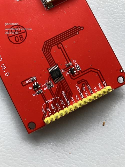
On my three ILI9488 3.5" displays marked V1.0 the LED pin8 connects to the J3Y transistor base (having checked the datasheet pinouts) and draws just 4mA. As Mick noted above there's a 1K resistor on the J3Y base so having a low value resistor, (47Ohm in my case) coming from 5v does almost nothing. Because of previous threads I had wrongly assumed the backlight was fed directly from the pin1 5v supply and thus required the resistor but it now looks like we're feeding the backlight with 3.3v from the onboard regulator anyway.  Greg |
||||
| lizby Guru Joined: 17/05/2016 Location: United StatesPosts: 3150 |
I had just looked at my new ILI9488s and noticed the same thing. So for the ILI9488, if you connect to a pin, and PWM it, what is the likely effect going to be of it passing through the 3V3 regulator? (I had had the low Ohm resistor (47R) feeding from 3V3 and have not felt the need to be able to brighten or dim.) PicoMite, Armmite F4, SensorKits, MMBasic Hardware, Games, etc. on fruitoftheshed |
||||
| Mixtel90 Guru Joined: 05/10/2019 Location: United KingdomPosts: 6798 |
If you have a display where a transistor is being used for the backlight, and there is a base resistor of 1k or so, than connecting an external 47R or 68R resistor is going to make no discernable difference to the brightness at all - if any. I've not checked whether the backlight +ve is connected to 3V3 (after the regulator) or 5V (before the regulator) on the displays that I have. Mick Zilog Inside! nascom.info for Nascom & Gemini Preliminary MMBasic docs & my PCB designs |
||||
| stanleyella Guru Joined: 25/06/2022 Location: United KingdomPosts: 2129 |
Why dim it? It's dim enough :) |
||||
| Mixtel90 Guru Joined: 05/10/2019 Location: United KingdomPosts: 6798 |
< Mick sends Stan a Specsavers gift voucher >  Mick Zilog Inside! nascom.info for Nascom & Gemini Preliminary MMBasic docs & my PCB designs |
||||
| stanleyella Guru Joined: 25/06/2022 Location: United KingdomPosts: 2129 |
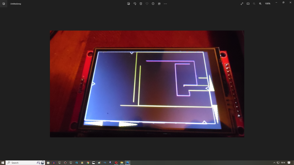
I get goggles from pound land. Ili has narrow viewing angle so can look dim in daylight. I'm not moaning, I like ili displays  |
||||
| paceman Guru Joined: 07/10/2011 Location: AustraliaPosts: 1329 |
Here's some more grist for this mill. On my ILI9488 I put 5v on the pin1 supply and on the pin8 LED pin and got the expected white screen. With it running I then checked some voltages around the J3Y transistor. 4.2v shows up at the input base of J3Y so the 0.8v drop across the onboard 1K resistor indicates about 4mA which is what I previously measured going into pin8. 3.3v on pin8 also worked fine. So far so good. I then checked the emitter and collector pins on J3Y and found 0.03v and 0.07v respectively. Also further into the rabbit hole the 8.2K resistor from the collector had around 0.65v going in and approx 0.54v coming out. This seems a bit weird because it equates to a tiny 0.01mA current flow, obviously not enough to drive the backlights. I wondered if there might be some high-ish frequency internal PWM'ing going on which might then be gated by any PWM signal imposed on pin8 from the Pico so checked for it with the 'scope but couldn't see anything on the 8K2 output. It now looks like the transistor is purely there to allow for 3.3v or 5v input to pin8, how the rest works I've no idea but I'm sure a few of you others can let me know. Greg |
||||
| Mixtel90 Guru Joined: 05/10/2019 Location: United KingdomPosts: 6798 |
The collector resistor is almost certainly 8R2, not 8K2. There is a volt drop of 0.11V across it so the backlight current is about 13mA. I say approximately because the resistor probably isn't exactly 8R2. :) 13mA still sounds low to me, but it's quite possible. Edited 2023-07-09 21:50 by Mixtel90 Mick Zilog Inside! nascom.info for Nascom & Gemini Preliminary MMBasic docs & my PCB designs |
||||
| stanleyella Guru Joined: 25/06/2022 Location: United KingdomPosts: 2129 |
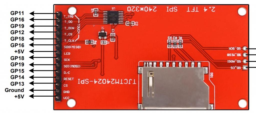
The display in the mmbasic manual looks like no transistor but no mention of a current limiting resistor for the led. It would be better if there was no led pin and just 5V supply as you can't see anything without the backlight so it's not optional.  |
||||
| Mixtel90 Guru Joined: 05/10/2019 Location: United KingdomPosts: 6798 |
I have a feeling (and only a feeling!) that R6 in that photo might be an 8R2 limiting resistor for the backlight. If so, connecting LED directly to 5V is fine. I haven't got one of these displays so I can't check. Mick Zilog Inside! nascom.info for Nascom & Gemini Preliminary MMBasic docs & my PCB designs |
||||
| phil99 Guru Joined: 11/02/2018 Location: AustraliaPosts: 2137 |
Hi Stan, On that photo you can see a track going from the LED pin to R4, which is providing the current limit so that one doesn't need an external resistor if you want maximum brightness. Some older ILI9341 displays have neither a transistor or resistor in the line so an external one must be used. Edit Yes Mick, looking closer it's R6. Edited 2023-07-09 22:40 by phil99 |
||||
| stanleyella Guru Joined: 25/06/2022 Location: United KingdomPosts: 2129 |
@phil, there's many different ili versions. I got 320x240 but the screen is bigger size on different boards. All mine have a transistor and they're years old so probably why running led pin from 3.3V or 5V no noticeable brightness change. |
||||
| paceman Guru Joined: 07/10/2011 Location: AustraliaPosts: 1329 |
Yes, my bad Mick it is 8R2 not 8K2 (on my ILI9488). The second decimal place on those voltages across it are pretty rubbery too along with the resistor perhaps being off. The 13mA could be well up but as you say it still seems low. I'd have expected more like 30-50mA. Greg Hmmm... and I also see I stuffed up with the reported current calculation. I like your 13mA better than my effort.  Edited 2023-07-09 23:49 by paceman |
||||
| Page 1 of 2 |
|||||