
|

|
Forum Index : Microcontroller and PC projects : Solar Battery fridge Controller
| Page 1 of 2 |
|||||
| Author | Message | ||||
| Bleep Guru Joined: 09/01/2022 Location: United KingdomPosts: 511 |
I have had a small solar panel and old car battery for a number of years, which I use to charge all of our mobile devices, torches, bike lights, cameras, the only problem was in the winter, the solar panel couldn't keep up with the demand in a UK winter, so I got a cheap second hand 40W panel and a couple of free half capacity 100Ah leisure batteries. Now I had far too much power in the summer, could I do anything useful with the excess? I had a small modified sine wave inverter, which was basically free, could I automatically run our fridge and or freezer from the excess power in the summer? Apparently using a PicoMite I can :-) I've attached circuit diagram, photos and code, if anyone cares to have a look. This is very specific to me, in that it allows for Economy 7 use over solar, if available, the inverter can in theory run both fridge and freezer together, it's about 1.2Kw (maybe), however both fridge and freezer take a hefty surge at start up, 50 to 60A from the battery, so my circuit/program sequences the fridge and freezer in turn, to prevent either of them stalling the other during power up, it also powers the inverter on for a couple of seconds before applying the load, again because of a quirk with the inverter that it ramped up it's output voltage, neither fridge or freezer liked this. I monitor Solar power IN and Inverter power OUT keeping running totals and if the inverter over currents it is shut off and tried again in 10 minutes, if after three attempts it still over currents the controller goes to fail safe and runs the fridges from the mains and raises an alarm. In full sun, not very likely in the UK, it will still put in too much power to the battery, in theory this does not matter, there is a separate battery charge controller, however this is a resistor shunt type, so gets quite hot, in this unlikely event my controller will run the inverter continuously, as an extra 750mA drain, otherwise the inverter is only on when needed. A couple of important totals are saved every hour, using VAR SAVE like Total Wh in/out and a couple of others, a log file is written to when a fault occurs and also every midnight. The code runs at an iteration rate of once per second, it did not need to be any faster, I also use the slowest CPU SPEED to save power, it takes about 5mA from the battery continuously, more when the relays are active, but then there is hopefully plenty of solar power. :-) The only control is a push switch, quick push for display on/off, long push to force the controller in to/out of battery charge only mode, so I can manually force a full battery charge, or bring it out of charge mode if required. The controller will only ever allow the battery to go to 50% discharge and will only start running the fridges from solar if the battery is reasonably charged and there is at least 2A coming from the panels, otherwise it uses mains power. I think that just about covers it, other than to say, this was really quite tricky, not from a software/hardware point of view, but because at one end you've got a couple of 12V 100Ah batteries capable of dumping kW of power in to a short circuit and at the other 240V mains supply! Great care required. Thanks to Geoff and Peter for enabling me to do this. Yes it will be going into a propper box, with display and push button on front, one day! Regards, Kevin. PS you could argue that this is in the wrong forum, but for me it was more about the electronics/software and control than it was the solar. Circuit diagram 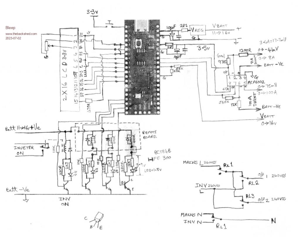 Circuit board 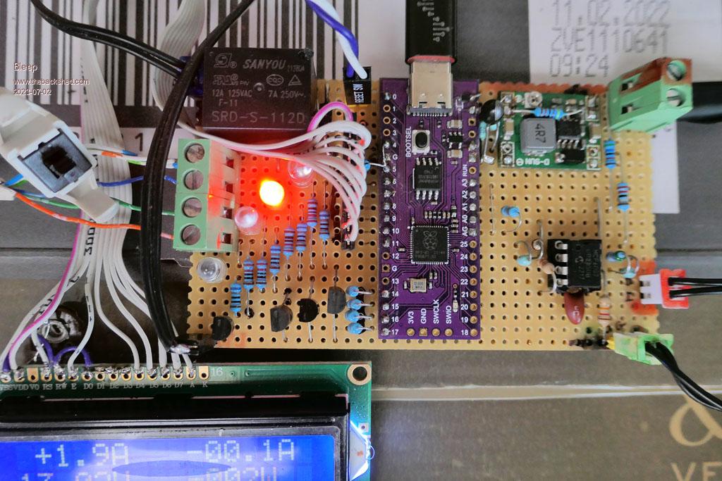 The display cycles through various modes, the top line always shows Input and Output current. Display showing Total accumulated input and output Wh  Display showing daily input and output Wh  Display showing Battery Voltage and current output Watts  My Solar very small panels, about 60W absolute max, normally in the UK about 45W max. 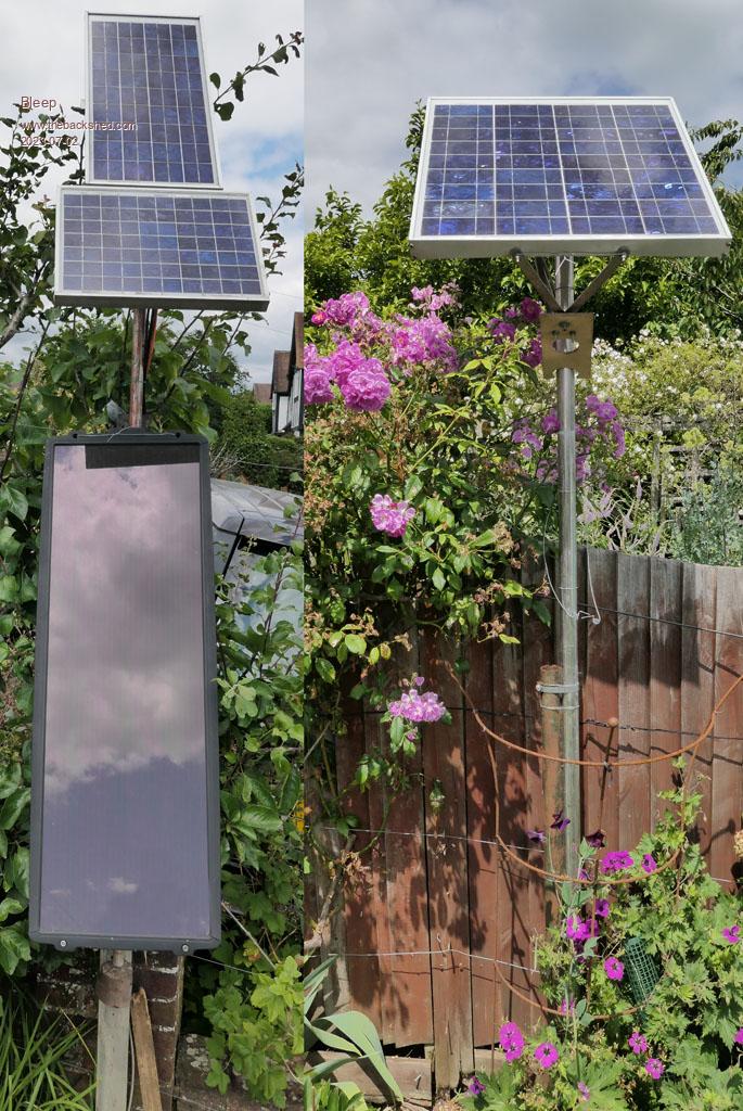 'Solar charge/discharge monitor & controler Option EXPLICIT Option DEFAULT NONE Option vcc 3.302 Timer =0 Const True=1 Const False=0 'set test flags Const test=False'for running with no hardware Const test2=True'for running with printing debug Const overload=20.0 Const noload=3.6 Const overvolt=14.05 Const battfull=13.5 Const battlow=12.45 Const wait4=4 Const wait6=6 Const wait12=12 Const go=2.00 Const wattsec=2.77777777E-4 Const sec=1000 Dim string txt 'battery cutoff voltage for 40% & 50% battery capacity at different currents 'Dim Float V40(4)=(12.38,12.2,11.8,11.3,11.0) '@1A,5A,10A,20A,33.3A 'Dim Float V50(4)=(12.4,12.25,12.0,11.5,11.2) '@1A,5A,10A,20A,33.3A Dim Float Iin(4),Volt(4),Iout(4),raw(4,2),hi(2),lo(2) Dim Float ipi,opi,outi,v,whr,wh(1),daywh(1),wkwh(1),mtwh(1) Dim Float tot(2),last(2),filter(3,2) 'opamp offset, Input I, Output I, Batt Voltage Dim Float offset(2)=(-0.0400,-0.0370,-0.008) 'Dim Float offset(2)=(-0.0395,-0.0365,-0.008) 'scaling factor Input I, Output I, Batt Voltage Dim Float scale(2)=(2.27,28.25,6.795) 'Dim Float scale(2)=(2.28,28.50,6.802) 'Dim Float cor2(2)=(1.0,0.995,1.00) Dim Integer x,y,tick,filt,idle,charging=0,P1,P2,relay,displ=1,displc Dim Integer overld,alarm,invon=0,mainsoff,mainsrun,status=3,div(2) Dim Integer t1=0,t2=-4,rund=0,runon,loopt=sec,hr,lhr=25,show=3,day If test Then ' wh(0)=4024:wh(1)=3570 ' daywh(0)=330:daywh(1)=-220 ' wkwh(0)=1200:wkwh(1)=-1002 ' mtwh(0)=4500:mtwh(1)=-3500 ' day=0 Const rundly=15000'600000'15000 Const overun=30'3600'30 Const hr6=4'21000 Else SetPin GP25, DOUT SetPin GP14, DOUT SetPin GP15, DOUT SetPin GP16, DOUT SetPin GP17, DOUT SetPin GP5, DOUT SetPin GP26,AIN SetPin GP27,AIN SetPin GP28,AIN SetPin GP0,DIN,Pulldown Const rundly=600000 Const overun=3600'5400 Const hr6=21000 EndIf VAR Restore 'end program with all outputs off if program failed. If MM.Watchdog Then status=4 Else ADC open 166666, 3 EndIf 'keep going as long as no major faults Do While status<>4 WatchDog 2000 'Take 5 readings, find the max and min and remove them 'sum the remaining values and divide by number of readings used. 'Do this 4 times and then do the same again on those 4 values For filt=0 To 3 ADC Start Iin(0),Volt(0),Iout(0) Math Insert raw(),,0,Iin():Math Insert raw(),,1,Iout():Math Insert raw(),,2,Volt() 'loop for each input, I in, I out, Volts. For y=0 To 2 tot(y)=0:div(y)=0 'use the first readings as hi & low initially hi(y)=raw(0,y):lo(y)=raw(0,y) 'now check the rest For x=1 To 4 ' Print raw(x,y), If hi(y)<raw(x,y) Then hi(y)=raw(x,y) If lo(y)>raw(x,y) Then lo(y)=raw(x,y) Next 'Print hi(y),lo(y), For x=0 To 4 If raw(x,y)< hi(y) And raw(x,y)>lo(y) Then Inc tot(y),raw(x,y):Inc div(y) Next If div(y) Then filter(filt,y)=tot(y)/div(y) Else filter(filt,y)=hi(y) EndIf 'Print filter(filt,y) Next Next ' Filter out high and low readings again. For y=0 To 2 div(y)=0:tot(y)=0 'use the first readings as hi & low initially hi(y)=filter(0,y):lo(y)=filter(0,y) 'now check the rest For x=1 To 3 If hi(y)<filter(x,y) Then hi(y)=filter(x,y) If lo(y)>filter(x,y) Then lo(y)=filter(x,y) Next For x=0 To 3 If filter(x,y)<hi(y) And filter(x,y)>lo(y) Then Inc tot(y),filter(x,y):Inc div(y) Next Next For y=0 To 2 If div(y) Then tot(y)=tot(y)/div(y) Else tot(y)=hi(y) EndIf 'Add in ADC correction at low voltages. ' If tot(y)< 0.15 Then tot(y)=tot(y)*cor2(y) 'Print tot(y); 'Initialise 'last' values ' If last(2)<0.00001 Then last(y)=tot(y) 'rolling average over last 2 readings ' tot(y)=tot(y)*0.5+last(y)*0.5 ' If tot(y)<0.0 Then tot(y)=0.0 Next Inc tick ' Debug If test Then 'input current tot(0)=0.039 ' If tick>5 Then tot(0)=0.91 ' If tick>90 Then tot(0)=0.0 'output current tot(1)=0.036 ' If tick>42 Then tot(1)=0.22 ' If tick>52 Then tot(1)=0.22 ' If (tick>40 And tick<45) Or (tick>70 And tick<75) Or (tick>100 And tick<105) Then tot(1)=1.0 tot(2)=1.9 ' If tick>5 Then tot(2)=2.2 ' If tick>30 Then tot(2)=1.9 ' If tick>40 Then tot(2)=1.6 ' If tick>50 Then tot(2)=1.6 ' If tick>60 Then tot(2)=1.6 ' Print tot(0),tot(1),tot(2),Time$ 'Print Time$ EndIf Print tot(0),tot(1),tot(2),Time$ 'remove opamp offset, then scale up. ipi=(tot(0)+offset(0))*scale(0) 'Shunt=0-100A=0-75mV*47(gain)=0-3.5V opi=(tot(1)+offset(1))*scale(1) 'Shunt=0-8A=0-41mV*81(gain)=0-3.32V 'calc outi for battery voltage compensation against drain current. outi=opi-ipi 'current out very low or negative If outi<0.01 Then outi=0.1 'current out over 20A, adjust compensation(for 2x50A Batteries). ElseIf outi>20 Then outi=20.0+(outi-20.0)*0.45 EndIf v=(tot(2)+offset(2))*scale(2) 'calculate Watt second for input current whr=ipi*v*wattsec 'add up Watt seconds to give Wh Inc daywh(0),whr Inc wh(0),whr 'calculate Watt second for output current whr=-opi*v*wattsec 'add up Watt seconds to give Wh Inc daywh(1),whr Inc wh(1),whr If Not test Then If Pin(GP5) Then If charging Then Bitbang lcd 1,1,"C"+Format$(ipi,"%+04.1f")+"A "+Format$(-opi,"%+05.1f")+"A" Else Bitbang lcd 1,2,Format$(ipi,"%+04.1f")+"A "+Format$(-opi,"%+05.1f")+"A" EndIf If tick>show+3 Then show=tick+3 'show for 3 seconds If tick<show Then Bitbang lcd 2,1,Format$(v,"%5.2f")+"V "+Format$((v*(-opi)),"%+04.0f")+"W " 'show for 2 seconds ElseIf tick<show+2 Then If wh(0)>9999 Or wh(1)>9999 Then Bitbang lcd 2,1,Format$(wh(0),"%+06.0f")+"Wh"+Format$(wh(1),"%+06.0f")+"Wh" ElseIf wh(0)>999 Or wh(1)>999 Then Bitbang lcd 2,1,Format$(wh(0),"%+05.0f")+"Wh "+Format$(wh(1),"%+05.0f")+"Wh " 'show for 2 seconds Else Bitbang lcd 2,1,Format$(wh(0),"%+04.0f")+"Wh "+Format$(wh(1),"%+04.0f")+"Wh " EndIf Else Bitbang lcd 2,1,Format$(daywh(0),"%+04.0f")+"Wh "+Format$(daywh(1),"%+04.0f")+"Wh " EndIf EndIf EndIf 'status=1 Running-Inverter ON, 1 o/p relay ON, mains relay ON (mains OFF). 'status=2 Standby-Inverter OFF, o/p relays OFF, mains relay ON (mains OFF). 'status=3 Battery low, or recharge mode, all relays OFF (mains ON). 'status=4 Fault-Inverter OFF, o/p relays OFF, mains relay OFF (mains ON). 'status=5 Sun gone, inverter OFF, run fridges every 3hrs, untill 24:00 then all ON over night. 'Control of the inverter & 2 relay outputs 'runtimer toggle If t1<Timer Then t1=Timer+rundly : rund=Not rund 'loop counter timer Inc t2 'has the battery been put in charge mode? If charging Then 'check if voltage has risen enough to stop charging only mode? If v>battfull Then charging=False:status=2:invon=False:P1=0:P2=0:relay=0 t2=0:t1=Timer+rundly:rund=True EndIf EndIf 'check for electricity cheap rate time 00:00 to 08:00 BST 'get the current hour hr=Val(Left$(Time$, 2)) 'has the hour changed If hr<>lhr Then 'standard hourly update VAR Save wh(),daywh(),status EndIf 'if still cheap rate electricity stay on mains power and charging If hr>=8 Then 'is the solar input current good or battery full and not in recharge mode. If (ipi>go Or v>battfull) And Not charging Then 'Set an overun timer, so system runs if the sun has been out in this hour 'Is this the first time for a while If tick>runon Then 'Give our selves an overun runon=tick+overun 'Reset other timer. t2=0:t1=Timer+rundly:rund=True status=2 'Keep setting the overun timer, all the time the sun is out. Else If hr<16 Then 'before 4pm set the runon runon=tick+overun Else 'later then 4pm then halve the runon runon=tick+overun*0.5 EndIf EndIf EndIf 'sun gone and timed out If tick>=runon Then 'after 4pm but not enough sun If hr>=16 Then status=5 'is it 6pm or 9pm? If hr=18 Or hr=21 Then If Not mainsrun Then invon=False:t2=0:t1=Timer+rundly:rund=True 'run fridges for an hour mainsrun=True Else 'turn off fridges for remainder mainsrun=False EndIf 'not enough sun, before 4pm, run fridges normally from mains. Else If status<>3 Then status=3:P1=1:P2=1:invon=False:t2=0:t1=Timer+rundly:rund=True EndIf EndIf 'before 8am, run fridges from mains Else If status<>3 Then status=3:P1=1:P2=1:invon=False:t2=0:t1=Timer+7000:rund=True EndIf 'are we in a normal running mode? If status=1 Or status=2 Then 'turn off mains power mainsoff=True 'check if Sun has gone, power down, just charge battery. If tick>=runon Then status=3 t2=0:t1=Timer+rundly:rund=True invon=False:P1=1:P2=1 EndIf ' are we in an inverter on mode? If status=1 Then Inc invon 'Batt v good (2x50A Batts) adjusted for load Or no significant load(fridge OFF) Or wait to avoid volt dip? If v>battlow-outi*0.05 Or opi<noload Or t2<wait6 Then 'Current drain good, or wait a bit to avoid surge? If opi<overload Or t2<wait4 Then 'Reset overload if no overload and an extended delay to be sure things have settled If opi<overload And t2>wait12 Then overld=False EndIf 'has the inverter powered up? If invon>4 Then 'is the load off or no relays active, Or after run delay. If ((opi<noload Or relay=0) And t2>wait4) Or (Not rund) Then 'swap over the loads, reset the timers. Select Case relay Case 0 P1=1:P2=0:relay=1:t2=0 Case 1 P1=0:P2=1:relay=2:t2=0 Case 2 P1=0:P2=0:relay=0:status=2:t2=0 End Select t1=Timer+rundly:rund=True EndIf 'inverter off EndIf 'overload Else 'turn off everything, increment overload counter. P1=0:P2=0:invon=False Inc overld 'set alarm, turn OFF inverter. If overld>2 Then invon=False status=4 alarm=True t2=0:t1=Timer+rundly:rund=True Else status=2 'decrement relay, so that same output is tested again after it overloaded. If relay>0 Then Inc relay,-1 EndIf 'save overload stuff to log Open "solar.log" For Append As #1 Print #1, Date$" "Time$" "Format$(daywh(0),"%4.0f")" "Format$(wh(0),"%6.0f")"Wh In "Format$(daywh(1),"%4.0f")" "Format$(wh(1),"%6.0f")"Wh Out stat="status Close #1 'save status to non-volatile memory VAR Save wh(),daywh(),status 'wait before trying again t1=Timer+rundly:rund=True EndIf 'low battery, status mode is 3 all off, activate charge. Else charging=True:status=3 runon=tick t2=0:t1=Timer+rundly:rund=True invon=False:P1=1:P2=1 'save charge state stuff to log Open "solar.log" For Append As #1 Print #1, Date$" "Time$" "Format$(daywh(0),"%4.0f")"Wh In "Format$(daywh(1),"%4.0f")"Wh Out "Format$(v,"%5.2f")"Batt V "Format$(opi,"%5.2f")"Batt I stat="status Close #1 EndIf 'status mode is 2 standby Else 'wait for a delay, then start sequence again. If Not rund Then status=1 t2=0:t1=Timer+rundly 'If we are here because of an overload If overld>0 Then rund=False Else rund=True EndIf Else 'run inverter continuously as a sink if too much sun! If (v>overvolt Or (v>(overvolt-0.6) And invon<>0)) And overld=False Then Inc invon If opi>overload And t2>=wait4 Then Inc overld Else invon=False EndIf EndIf EndIf 'Not mode 5 run fridges from mains after sun gone. ElseIf status=5 Then 'turn off the inverter invon=False 'run fridges every few hours If mainsrun Then 'OFF toggle mode If rund Then If Not mainsoff Then mainsoff=True ElseIf mainsoff And (P1 Or P2) Then 'mains off, Fridges set to mains input(OFF) P1=0:P2=0 Else 'default to mains input OFF, fridges set to mains input(OFF) P1=0:P2=0:mainsoff=True EndIf 'On toggle mode Else If mainsoff And Not(P1 And P2) Then 'inverter OFF, mains input OFF, Fridges set to inverter(OFF) P1=1:P2=1 ElseIf mainsoff And P1 And P2 Then 'mains input ON, fridges set to inverter(OFF) mainsoff=False ElseIf Not mainsoff And P1 And P2 Then 'mains input On, fridges set to mains(ON) P1=0:P2=0 Else 'Default to all runniing from mains input mainsoff=False:P1=0:P2=0 EndIf EndIf Else 'inverter OFF, mains OFF, Fridges set to mains(OFF) P1=0:P2=0:mainsoff=True EndIf 'mode 3 Or 4 Else ' delay for a time before switching back to mains, allows compressor to de-compress. If t2>wait4 And P1 And P2 Then mainsoff=False If Not rund Then P1=0:P2=0 'So that the system starts initialised off invon=False:relay=0 EndIf If Not test Then Pin(GP14)=invon>0 'inverter power on Pin(GP15)=mainsoff 'remove mains power from outputs Pin(GP16)=P1 'Power output 1 (either mains or inverter) Pin(GP17)=P2 'Power output 2 (either mains or inverter) 'Power up and initialise the LCD If hr=7 And lhr=6 Then 'only do once per day or when button pressed displ=True ElseIf hr=20 And lhr=19 Then 'only do once per day Or when button pressed displ=False EndIf If displ And Not Pin(GP5) Then Pin(GP5)=1 'display backlight Pin(GP4)=1 'LCD module power Bitbang lcd init GP8,GP9,GP10,GP11,GP6,GP7 Bitbang lcd Clear ElseIf Not displ And Pin(GP5) Then Bitbang lcd Close Pin(GP5)=0 'display backlight Pin(GP4)=0 'LCD module power EndIf EndIf If Test2 Then Print Format$(ipi,"%4.2f")"A in "Format$(opi,"%4.2f")"A out "Format$(v,"%5.2f")"V "; Print Format$(wh(0),"%5.0f")"Wh in "Format$(wh(1),"%5.0f")"Wh out "Timer/sec" "Time$ Print "invon="invon" P1="P1" P2="P2" relay="relay" mainsoff="mainsoff" stat="status Print "charging="charging" overload="overld" alarm="alarm" t1="t1" t2="t2" rund="rund"" EndIf 'loop untill 1 second is up Do While Timer<loopt If Not Test Then 'is button pressed If Pin(GP0) Then Inc displc 'short press, turn on/off display If displc=2 Then displ=Not displ 'long press If displc=15 Then 'not currently in charge mode If charging=False Then 'initiate charge mode charging=True:status=3 runon=tick:t2=0:t1=Timer+rundly:rund=True invon=False:P1=1:P2=1 'in charge mode Else 'turn off charge mode, run inverter for half an hour. charging=False:status=2:invon=False:P1=0:P2=0:relay=0 runon=tick+overun*0.5:t2=0:t1=Timer+rundly:rund=True EndIf EndIf Else displc=0 EndIf EndIf Pause 50 Loop 'add one second to timer, for the next loop. Inc loopt,sec 'just after midnight to allow relays to all relax, so all power from mains 'internal clock corrections, save daily log then sleep for 6 hours If hr=0 And t2=10 Then Time$="00:00:09" 'just after midnight loose 2 seconds 'update Wh totals Inc wkwh(0),daywh(0) Inc wkwh(1),daywh(1) Inc mtwh(0),daywh(0) Inc mtwh(1),daywh(1) Inc day 'save stuff to log Open "solar.log" For Append As #1 If day=7 Or day=14 Or day=21 Then Print #1, Date$" D"Format$(daywh(0),"%4.0f")" W"Format$(wkwh(0),"%5.0f")" T"Format$(wh(0),"%6.0f")"Wh In D"Format$(daywh(1),"%4.0f")" W"Format$(wkwh(1),"%5.0f")" T"Format$(wh(1),"%6.0f")"Wh Out "Format$(v,"%5.2f")"V stat="status VAR Save wkwh(),mtwh(),day wkwh(0)=0:wkwh(1)=0 ElseIf day>27 Then Print #1, Date$" W"Format$(wkwh(0),"%5.0f")" M"Format$(mtwh(0),"%6.0f")" T"Format$(wh(0),"%6.0f")"Wh In W"Format$(wkwh(1),"%5.0f")" M"Format$(mtwh(1),"%6.0f")" T"Format$(wh(1),"%6.0f")"Wh Out "Format$(v,"%5.2f")"V stat="status day=0 VAR Save wkwh(),mtwh(),day wkwh(0)=0:wkwh(1)=0 mtwh(0)=0:mtwh(1)=0 Else Print #1, Date$" D"Format$(daywh(0),"%4.0f")" T"Format$(wh(0),"%6.0f")"Wh In D"Format$(daywh(1),"%4.0f")" T"Format$(wh(1),"%6.0f")"Wh Out "Format$(v,"%5.2f")"V stat="status VAR Save wkwh(),mtwh(),day EndIf Close #1 daywh(0)=0:daywh(1)=0 WatchDog OFF CPU SLEEP hr6 loopt=Timer+sec EndIf 'update last hour to current lhr=hr 'repeat whole program Loop 'status=4 major fault 'disable all outputs, display error message. Pin(GP14)=0 Pin(GP15)=0 Pin(GP16)=0 Pin(GP17)=0 If Not Pin(GP5) Then Pin(GP5)=1 'display backlight Pin(GP4)=1 'LCD module power Bitbang lcd init GP8,GP9,GP10,GP11,GP6,GP7 Bitbang lcd Clear EndIf If MM.Watchdog Then Bitbang lcd 1,1,"Program Halted " Else Bitbang lcd 1,1,"Serious Fault " WatchDog OFF EndIf Bitbang lcd 2,1,"Check Log File " End Edited 2023-07-02 01:13 by Bleep |
||||
| lizby Guru Joined: 17/05/2016 Location: United StatesPosts: 3150 |
Thanks for posting this. Can you explain in words how you ramp up to keep the power-on surge from stalling out the fridge and freezer on startup? (I know that if I examined the code closely, I would find that, as one of my old bosses said, "The best documentation is a working program".) PicoMite, Armmite F4, SensorKits, MMBasic Hardware, Games, etc. on fruitoftheshed |
||||
| robert.rozee Guru Joined: 31/12/2012 Location: New ZealandPosts: 2350 |
hi Bleep, one thing you need to be very careful with is mains arcing from N.O to N.C contacts when a relay switches over. what happens (under load) is that as the common contact disconnects from N.O (or N.C) contact, it draws an arc which is maintained during the transit time to the opposite contact. depending on the setup, the result can be a rather loud bang! bear in mind that as your inverter and the mains are not synchronized, at any instant there could be 680v (1.4 x 2 x 240) between Inverter Live and Mains Live (and the same for the Neutrals). in the past i've got around this using an extra pair of small signal relays wired such that a 'turn on' signal can not get through the signal relay until the currently energized main relay is open. this involves using main relays with 3 sets of contacts. it is always advisable to rely upon such mechanical interlocks rather than electronic controls. cheers, rob :-) |
||||
| phil99 Guru Joined: 11/02/2018 Location: AustraliaPosts: 2137 |
If I have understood Bleep he is trying to avoid the ramp-up. The inverter ramps the voltage up but the compressor motors don't like that at all, so their switch on is delayed till after max voltage is reached. Each has a different delay so the start surges don't overlap. A delay before starting is also desirable to allow the start winding thermistor to cool down. In the old days a current solenoid relay activated the start winding whenever the current was much above normal running current. To save money now they use a PTC thermistor to briefly energize the start winding. If the PTC is still hot it won't start and trips the overload. Yes, you need two relays. Edit Or at least separate NO and NC contact sets in the one relay, provided one opens well before the other closes. Edited 2023-07-02 18:39 by phil99 |
||||
| Mixtel90 Guru Joined: 05/10/2019 Location: United KingdomPosts: 6798 |
For mains changeover you can get proper mechanically and electrically interlocked pairs. ABB do a neat setup. Two standard "contactor" relays with a mechanical interlock module that fits neatly between them. Each relay has a normally closed contact that you wire in series with the opposite coil. It's impossible to pull both in together or even mechanically push them both in. This arrangement has been in use for many years. Software interlocking is not allowed under any circumstances. When doing a changeover there should *always* be a clean break, enforced by a timer (IIRC the minimum break time should be 200ms but it's a long time ago...). Note that ordinary break-before-make changeover contacts are not considered suitable for mains changeover, but it's sometimes done in control circuits where the two supplies have low current fuses. The alternative is to synchronise both supplies before a no-break changeover. (Un)happy memories of messing around with this stuff for many years.... :) Edited 2023-07-02 19:40 by Mixtel90 Mick Zilog Inside! nascom.info for Nascom & Gemini Preliminary MMBasic docs & my PCB designs |
||||
| lizby Guru Joined: 17/05/2016 Location: United StatesPosts: 3150 |
I'm afraid I don't understand that. I ask because I attempted a cycle-slicing ramp up with a PICAXE to start my sump pump from a battery in the event of a power outage--but didn't implement once I realized that the battery was pitifully insufficient for the length of time the pump was likely to run (the last time it came on during two days of heavy rain it ran almost continually for a day and a half--fortunately there was no power outage). I used these zero-crossing detector triac modules -- triac module -- with beefed up triacs. I got as far as proof of concept ramping up a 1500W 120V heater (not the same kind of demand, I know) before I realized how little run time I would get with the sump pump. PicoMite, Armmite F4, SensorKits, MMBasic Hardware, Games, etc. on fruitoftheshed |
||||
| phil99 Guru Joined: 11/02/2018 Location: AustraliaPosts: 2137 |
A ramp-up is perfect for resistive and capacitive loads, universal motors are happy with it too but single phase induction motors not so much. The start thermistor used on fridge and freezer compressors heats up and switches off the start winding before there is sufficient torque to turn the compressor. It draws a heap of current and trips the overload. They need full mains voltage instantly. |
||||
| lizby Guru Joined: 17/05/2016 Location: United StatesPosts: 3150 |
Are you saying that "slow start" cycle-slicing doesn't work on fridges and freezers because of their design, and that the "surge" current issue is different for them than for, say, a sump pump? (I ask out of ignorance--I know next to nothing about the different operating parameters of different types of motors.) PicoMite, Armmite F4, SensorKits, MMBasic Hardware, Games, etc. on fruitoftheshed |
||||
| Bleep Guru Joined: 09/01/2022 Location: United KingdomPosts: 511 |
To answer some/most of the above queries. There were several problems with the inverter. 1 It ramped up it's output voltage over about a second when turned on which neither compressor liked. 2 If a compressor was running and another cut in, the surge was such that the first compressor would often stall. 3 The inverter draws 0.75A even when doing nothing (significant for me), unless turned off. To over come this, the inverter is kept turned off unless needed. When the inverter is turned on, no load is put onto it until after a couple of second. Only one compressor is allowed to run at any one time. I constantly monitor the current drain out of the battery/solar panel so I can detect either a fault condition, or the fact that a fridge/freezer has turned off on its own. So the sequence is. Sufficient sun, mains removed with relay RL1, there is then a delay, the inverter is turned on, delay, compressor RL2 turned on for 10minutes OR the compressor itself turns off due to correct temperature being reached, RL2 turned off, RL3 turned on for 10 minutes OR compressor itself turns off due to correct temperature being reached, RL3 turned off, inverter turned off for 10 minutes, repeat until sun goes or battery gets to 50%. The 10minutes is arbitrary but both Fridge & Freezer usually cut out before this limit and both are maintaining good temperatures. This also overcomes any relay contact over voltage, because the inverter is never active when the mains relay is connected. When the mains is isolated, the inverter can turn on and the fridge switching is then all done with the other 2 relays. Under fault conditions, all relays relax, which equates to Inverter OFF, Mains ON, both outputs ON, so both compressors running off mains. My understanding of Fridge/Freezer compressors is that they always take a hefty surge current, initially, to get them going, once running they run at around 50-70W (in my case) trying to ramp them up simply does not work. Regards, Kevin. |
||||
| lizby Guru Joined: 17/05/2016 Location: United StatesPosts: 3150 |
Thanks for the explanation. Nice project--I like it. Are you powering the LCD from 2 pins--GPIO4 and GPIO5? ~ Edited 2023-07-03 03:56 by lizby PicoMite, Armmite F4, SensorKits, MMBasic Hardware, Games, etc. on fruitoftheshed |
||||
| Bleep Guru Joined: 09/01/2022 Location: United KingdomPosts: 511 |
Hi Lizby, Yes that is correct, I was originally hoping to power the back light off one O/P and power the module from another, but the volt drop from one O/P to power the module was too high, so I paralled them up. I have done this so I can turn the display on and off under software control, another power saving feature, the display will normally switch on at 8am and off at 8pm, but you can control it manually using a quick push on the button. Regards, Kevin. |
||||
| lizby Guru Joined: 17/05/2016 Location: United StatesPosts: 3150 |
Thanks. Does this EasyEDA Schematic look accurate, considering that the standard Pico module is used, and the 4-relay PCB module shown below is used (either screwed directly into the 11-pin socket (every other pin removed) or via cable using the 6-pin socket)? 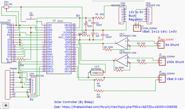 The relay module is from here: Aliex 4-relay module 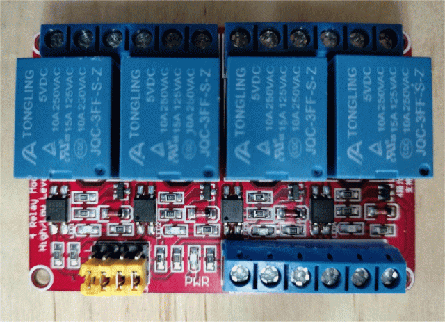 I like this module because it allows V+ as true, and if 5V is applied to DC+, then the 3V3 inputs work (but don't if DC+ is 3V3). PicoMite, Armmite F4, SensorKits, MMBasic Hardware, Games, etc. on fruitoftheshed |
||||
| Mixtel90 Guru Joined: 05/10/2019 Location: United KingdomPosts: 6798 |
I see the missed opportunity to use a nice, colour SPI LCD graphics display, c/w PWM backlight control and with a mimic diagram to show what's happening. ;) Treat it as a programming challenge.... :) Mind you, if you already had a text display in the drawer then you've made the right choice. "If something is going to cost you money then you're doing it wrong!" as someone or other once said. Or, at least, they should have. :) Mick Zilog Inside! nascom.info for Nascom & Gemini Preliminary MMBasic docs & my PCB designs |
||||
| lizby Guru Joined: 17/05/2016 Location: United StatesPosts: 3150 |
LOL LOL again. My parts boxes are overflowing, but I've never used a 16x2 or 20x4 LCD with the PicoMite, so I thought it would be interesting to try since Bleep had done all the hard work. Lots of pins free, so easy enough to add: 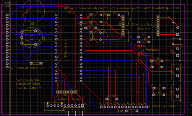 Choice of 16x2 or 20x4 LCD or ILI9341 or ILI9488 SPI LCD. PicoMite, Armmite F4, SensorKits, MMBasic Hardware, Games, etc. on fruitoftheshed |
||||
| Bleep Guru Joined: 09/01/2022 Location: United KingdomPosts: 511 |
Hi Lizby, few corrections to circuit. 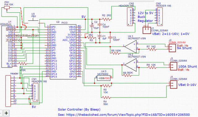 Power for the screen contrast pot should come from the switched power, not direct to the 3.3V as I'm unsure what would happen when the LCD module is powered off, but there is still power on the pot, probably nothing. Power for the PB1 comes from 3V3OUT, wasn't clear, but didn't look like it connected to anything, R3 was in the way. Power to the OpAmp should go through R3, extra smoothing and noise reduction. The Current shunts need to be connected as close as possible to the -Ve battery terminal, keeping all cables short and chunky, for example the power cables out of the 100A shunt, on mine, are effectivly short copper jump leads and the 100A shunt is bolted directly to the -Ve terminal. Batt -Ve terminal ^ +----------+ | +------------+ Solar Panel in>------+ 8A Shunt +->+>-+ 100A Shunt +-------->Power out +----------+ +------------+ | | | | J22 J21 J32 J31 Be careful, because the OpAmps are amplifying (relativly) low DC voltages, you have to worry about parasitic voltages popping up, just because a small, or large, current is flowing down a piece of wire. Regards, Kevin. |
||||
| Mixtel90 Guru Joined: 05/10/2019 Location: United KingdomPosts: 6798 |
The *really clever* way to deal with those op-amps is to put them in a screened box near the shunts and use a transistor to produce a current output rather than a voltage. A resistor at the Pico end converts the current back into a voltage. There are a couple of advantages - you aren't amplifying anywhere near as much stray noise induced into the op-amp inputs and, because it's a current loop, you can have long cable lengths on the output without voltage drop causing a problem. If you are *really really* clever you use the 3V3 supply to power the op-amps as well as sourcing the supply for the current loops. You should be able to power the op-amps from a decent supply rather than 3.3 if you are careful with the output. Mick Zilog Inside! nascom.info for Nascom & Gemini Preliminary MMBasic docs & my PCB designs |
||||
| Volhout Guru Joined: 05/03/2018 Location: NetherlandsPosts: 4247 |
Hi Bleep, Inputs like these always make me worry what would happen when something in the wiring is going wrong... or a short circuit happens... Just put some resistors here... Volhout PicomiteVGA PETSCII ROBOTS |
||||
| lizby Guru Joined: 17/05/2016 Location: United StatesPosts: 3150 |
Thanks for checking, Bleep. I can't say that the flow of my circuit diagram is very straightforward. I had already connected PB1 to the outbound side of R3; the MCP6002 is also connected there. I see what you mean about the pot--I'll fix that. Can you provide links for your shunts? Mick--sorry, but for circuits of this sort, I fall far short of *really clever*. PicoMite, Armmite F4, SensorKits, MMBasic Hardware, Games, etc. on fruitoftheshed |
||||
| Bleep Guru Joined: 09/01/2022 Location: United KingdomPosts: 511 |
Hi Volhout, Agreed, could presumably simply put 1k resistors in both those inputs as buffering, without affecting anything else. Regards Kevin. |
||||
| Bleep Guru Joined: 09/01/2022 Location: United KingdomPosts: 511 |
Hi Lizby, The 100A you can get anywhere, 100A giving 75mV, like this one. Ebay current shunt The 8A no, because I made it, from a 10A shunt out of a old multimeter, so it's just a short length of very slight resistance wire, I shortened it a bit then measured the voltage drop for a couple of currents. You could easily use a 10A shunt from that same link, but you would need to adjust the gain of that OpAmp. The current gain is set for 17.7mv @ 3.4A or 41.6mV @ 8A approx gain -64, the other OpAmp on the 100A shunt is a gain of approx 47. I also just remembered that I added two small 100nF capacitors, one across the 100K and the other across the 560K resistors on the OpAmps, again to get rid of ripple & interface, if you want to make your diagram completely correct. Regards Kevin Edited 2023-07-05 02:02 by Bleep |
||||
| Page 1 of 2 |
|||||