|

|
Forum Index : Microcontroller and PC projects : PicoMite: Can you run the red ILI9341 module for the Pico 3.3V output
| Author | Message | ||||
| thwill Guru Joined: 16/09/2019 Location: United KingdomPosts: 4043 |
Hi folks, Can anyone confirm or otherwise whether the red ILI9341 320x240 2.8" module can be powered from the Pico 3.3V output ? I thought you could ... ... I think I have ... but have I just been lucky ? Also the onboard SD card. Best wishes, Tom Game*Mite, CMM2 Welcome Tape, Creaky old text adventures |
||||
| stanleyella Guru Joined: 25/06/2022 Location: United KingdomPosts: 2129 |
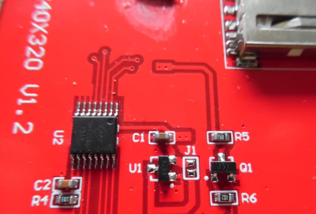
look at the back and j1. it shorts the 3.3V reg  |
||||
| stanleyella Guru Joined: 25/06/2022 Location: United KingdomPosts: 2129 |
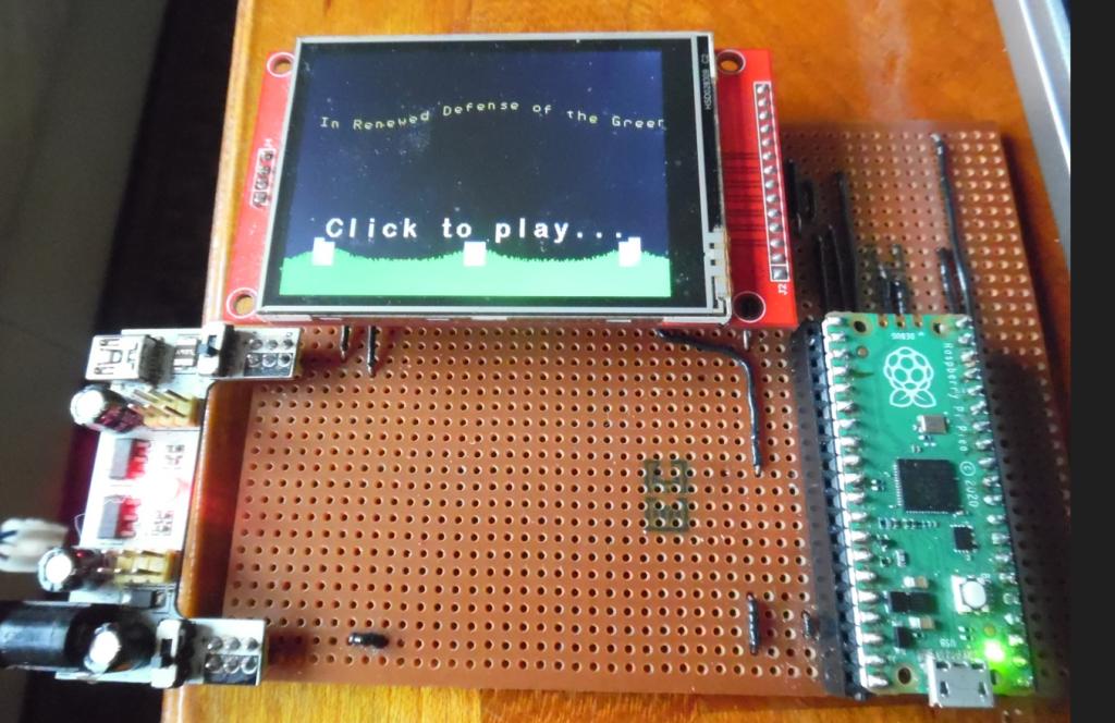
I turned the switch on my 5V to 3.3V ... which was for the display only , and it works ?!? sorry can't help more :(  ie it does work off 3.3v... but then there's voltage drop if the reg cuts off so 2.7V? Edited 2023-05-24 05:00 by stanleyella |
||||
| Volhout Guru Joined: 05/03/2018 Location: NetherlandsPosts: 4250 |
Hi Tom, There are 4 circuits on the red ILI0341 LCD board: 1/ The SD card. The SD card is normally powered from the 3.3V from the picomite. 2/ The touch controller. This is a 3.3V chip 3/ The LCD chip (the ILI9341), this is a 3.3V chip 4/ The backlight LED. Circuits 2 and 3 can be run from the pico 3.3V regulator when you short the J1 jumper Maybe even without shorting it, since the regulator will output roughly 2.9V when powered from 3.3V. And with 2.9V both chips should still work. But... (I just measured it on my board to be sure of this). The backlight LED has lower brightness at 3.3V. You may want to test this first. I normally have it connected to 5V through a resistor. When I connected it directly to 3.3V (no resistor) it worked, bus was not as bright as 5V. Volhout Edited 2023-05-24 05:07 by Volhout PicomiteVGA PETSCII ROBOTS |
||||
| lizby Guru Joined: 17/05/2016 Location: United StatesPosts: 3150 |
All of my PicoMite LCD designs for ILI9341 and ILI9488 have run off of 3V3 with a 47R resistor to backlight. PicoMite, Armmite F4, SensorKits, MMBasic Hardware, Games, etc. on fruitoftheshed |
||||
| thwill Guru Joined: 16/09/2019 Location: United KingdomPosts: 4043 |
Thanks folks, I just has the horrible thought that the new Bintendo Tomboy PCB (coming soon) had a fatal flaw ... it doesn't. Best wishes, Tom Edited 2023-05-24 05:36 by thwill Game*Mite, CMM2 Welcome Tape, Creaky old text adventures |
||||
| stanleyella Guru Joined: 25/06/2022 Location: United KingdomPosts: 2129 |
but as thwill said ". but have I just been lucky ?" ..and me as I don't use a 50R for the backlight, just run it off 3.3V |
||||
| Mixtel90 Guru Joined: 05/10/2019 Location: United KingdomPosts: 6798 |
IIRC the LCD pin on the ILI9341 (the later versions at least) is only connected to the base of a transistor via a resistor (1K springs to mind). The backlight LEDs are its collector load from VCC. That's why you can switch the backlight on and off or PWM it from a PicoMite pin. There's no way to dim the display with a resistor unless you put it in series with VCC. Trying to dim the display by starving the switching transistor of base current could lead to it frying. Connecting LCD to a supply via a 50R resistor will do no harm, but it won't affect the brightness. You can simply short it to VCC (3V3 or 5V) if you don't want to control it. Edited 2023-05-24 07:11 by Mixtel90 Mick Zilog Inside! nascom.info for Nascom & Gemini Preliminary MMBasic docs & my PCB designs |
||||
| stanleyella Guru Joined: 25/06/2022 Location: United KingdomPosts: 2129 |
I meant I'm lucky without resistor and "led" pin to 3.3V it not blown leds so a resistor on all boards to be safe. I don't see the point of dimming these displays with a pwm signal. They're dim enough as they are :) It's because mmbasic works this display so well I soldered it as a permanent board.. ok, it's not vga but pretty cool. |
||||