|

|
Forum Index : Microcontroller and PC projects : Idea for an I2C joystick
| Author | Message | ||||
| Mixtel90 Guru Joined: 05/10/2019 Location: United KingdomPosts: 6812 |
This is work in progress. In theory it should work. The box is the 90mm x 70mm x 28mm one used for the PicoMite VGA mini. The analogue joystick module is cheap and easy to get, as are the two ICs. Unfortunately there's no tactile feedback from the joystick as it's analogue, but there is a good range of adjustment in sensitivity. These joystick modules are designed to be connected using Dupont connectors but that's probably nit possible here. However, if the right-angle pins can be removed there are pads that give a direct connection, otherwise soldered wire links can be put in to other pads. I did find a design that converts one of these joysticks to digital, also using a LM339, but my design doesn't need the joystick to be modified, uses one less resistor and, I think, is easier to lay out on the PCB. Original mechanical CAD design: joystick cad.pdf PCB design, in box: The little PCB with the buttons on it is mounted on three 6mm pillars. The connections are merely soldered bits of bare wire, not a plug and socket arrangement. Holes in the bottom of the case give access to the address switches and sensitivity control. Guide holes in the PCB allow the constructor to get the holes in the right place for these and the joystick. Circuit diagram: joystick.pdf Edited 2023-04-06 05:19 by Mixtel90 Mick Zilog Inside! nascom.info for Nascom & Gemini Preliminary MMBasic docs & my PCB designs |
||||
| thwill Guru Joined: 16/09/2019 Location: United KingdomPosts: 4047 |
Unless the creator has other ideas I suggest this be known as "The MickStick". Best wishes, Tom Edited 2023-04-06 06:04 by thwill Game*Mite, CMM2 Welcome Tape, Creaky old text adventures |
||||
| lizby Guru Joined: 17/05/2016 Location: United StatesPosts: 3152 |
Have you found an inexpensive joystick which provides decent (even adequate) fine control? I have found the ones which come in, say, the 37-in-one kits to be nearly useless--especially if you want to press them and record a position that you think you have moved to. I wasn't sure it could be reliable for much more than right/left/up/down. PicoMite, Armmite F4, SensorKits, MMBasic Hardware, Games, etc. on fruitoftheshed |
||||
| Turbo46 Guru Joined: 24/12/2017 Location: AustraliaPosts: 1611 |
My experience with the Wii Nunchuk shows that that particular device is too imprecise. So I don't expect that this small analogue joystick would be much better. I'll stick with the Atari style joystick. I have always thought that ALL retro computers that are likely to be used to play games should really include an Atari joystick interface. That includes all of the Maximites! There is ALWAYS too much kerfuffle choosing which pins to use when trying to retrofit it. Nobody can agree. (sorry for the off topic rant)  Bill Keep safe. Live long and prosper. |
||||
| Amnesie Guru Joined: 30/06/2020 Location: GermanyPosts: 396 |
In the first place we need games for the PicoMite VGA   But cool idea!  Greetings Daniel |
||||
Grogster Admin Group Joined: 31/12/2012 Location: New ZealandPosts: 9308 |
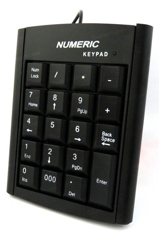
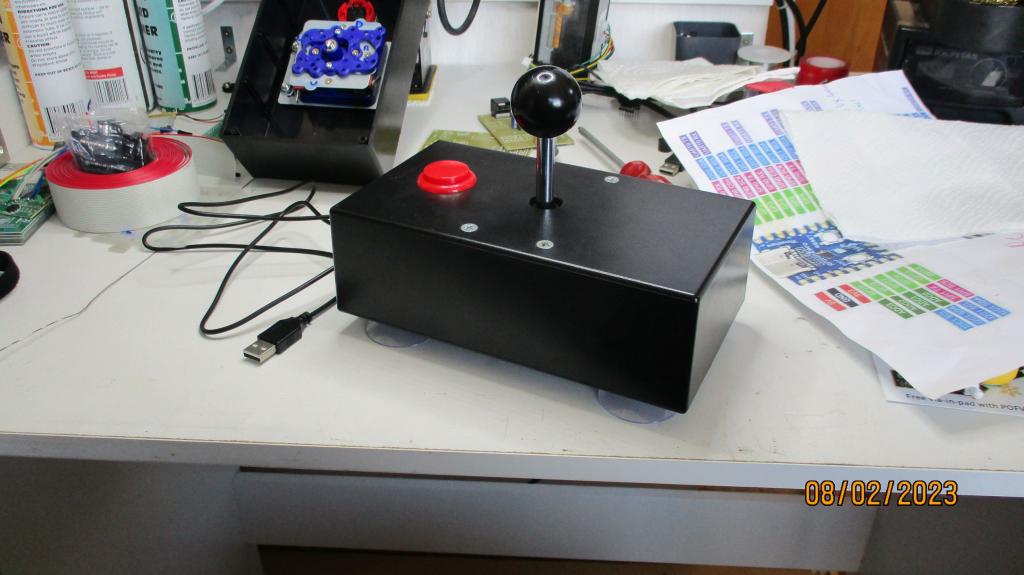
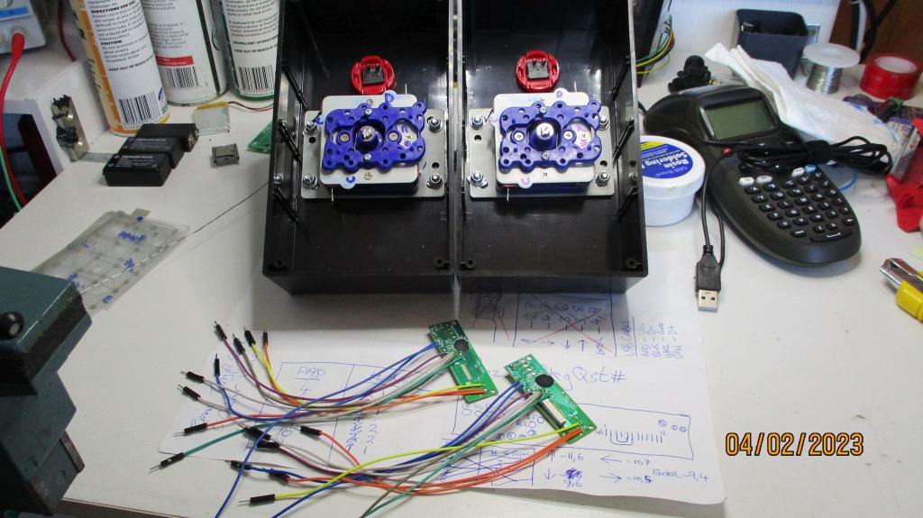
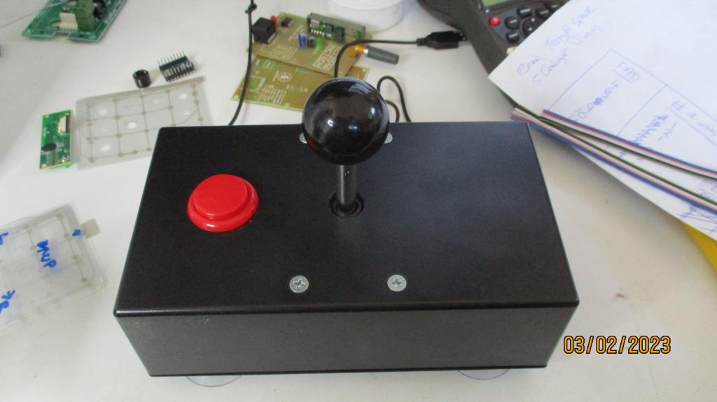
Although not an I2C joystick, in Feburary I did build a couple of USB joysticks out of numeric keypads to use with my Atari emulator for playing all the old 8-bit games. A bit big and ugly, but they work!      The advantage of the keypad controller, is that if you hold a key down, it auto-repeats, so you get an auto-fire function by just holding down the red fire button, and you don't have to rapidly bash the hell out of it. Although, some would say that makes the fire button authentic for the day, but many joysticks even then had an auto-fire switch on them. But I digress...... Smoke makes things work. When the smoke gets out, it stops! |
||||
| Mixtel90 Guru Joined: 05/10/2019 Location: United KingdomPosts: 6812 |
OOh! Those are great! I bet it costs more than 1.80 UKP just for one of those red balls though. :) Yes, these little joystick modules are the cheap & nasty ones provided with 37-in-one kits. However, they aren't being used as analogue. The analogue value is merely used for comparison with a voltage reference and *repeat* accuracy is ok. The switch is only used for Start, which is only usually used once per game so the fact that the joystick moves a bit when it's pressed probably doesn't matter. I've used them for two reasons, they are cheap and they are not made from unobtainium. I looked all over for some decent switched joystick modules but they are bulky and expensive. I looked at using D-pad components to make my own D-pad design, but you really need proper moulded cases and they aren't feasible in small quantities (and I haven't got access to a 3D printer or injection moulding machine). The main problems with this design are that there is no built-in hysteresis and that the "tilt activation window" (TAW) is square. That is pretty bad. The activation point is determined by the angle of tilt, not by the distance traveled by the top of the joystick. That means that the sensitivity is less on diagonal movement than it is in primary directions. A well-designed stick has a TAW that is circular and is two concentric circles. The outer one is the "must operate" distance and the inner one is the "must release" distance. It's quite possible to get round this, but you need a microcontroller. Something like a 18-pin 8-bit PIC would probably replace both the chips on the board and do the necessary calculation. So, the design as it stands is probably ok for 4-direction control but may be disappointing for 8-directions. The hysteresis problem may not bee too bad as it takes time for the stick to be read over I2C. EDIT: I've just checked and it should be possible to put a SMD PicoMite in to do the legwork. True integrated processing. :) It would be a I2C slave, of course, and handle all the inputs from the joysticks and buttons (pretending to be a MCP23008 in input-only mode). The main problem is the increased current drain, but as that can be at 5V (keeping the I2C at 3V3) it's not a great problem. . Edited 2023-04-06 17:42 by Mixtel90 Mick Zilog Inside! nascom.info for Nascom & Gemini Preliminary MMBasic docs & my PCB designs |
||||
Grogster Admin Group Joined: 31/12/2012 Location: New ZealandPosts: 9308 |
The old Atari/C64 joysticks were digital, and only had inputs for Left, Right, Up and Down. And Fire. A five-bit digital interface. There was nothing fancy with these and they MOSTLY only supported 4-direction. SOME games would poll the inputs and derive 8-direction, but most did not, and it was simply a case of grounding the up/down/left/right direction pins. And fire. Smoke makes things work. When the smoke gets out, it stops! |
||||
| Mixtel90 Guru Joined: 05/10/2019 Location: United KingdomPosts: 6812 |
PicoGAME (and its derivatives) works fine with Atari joysticks. I know 'cos I have one. :) That has the traditional 5-wire interface because I figured that it's the easiest to use. No special driver software required. The only problem is that it eats input pins unless you do stuff like diode isolation so that you can scan each stick. Mick Zilog Inside! nascom.info for Nascom & Gemini Preliminary MMBasic docs & my PCB designs |
||||
| thwill Guru Joined: 16/09/2019 Location: United KingdomPosts: 4047 |
FYI: Piotr's CMM2 G2 DX has an Atari joystick port (as well as 3 Nunchuk i2c ports). You can also connect a NES clone controller to the Atari port with a simple adapter; two of the pins need swapping. Best wishes, Tom Edited 2023-04-06 19:34 by thwill Game*Mite, CMM2 Welcome Tape, Creaky old text adventures |
||||
| Turbo46 Guru Joined: 24/12/2017 Location: AustraliaPosts: 1611 |
I have Piotr's CMM2 Deluxe and have built the interface to enable the connection of a NES controller to the joystick port. I was able to play Tom's Laser Cycle game with every one of the controllers that it supported. While I believe that Tom has chosen the best hysteresis values for the analogue joystick on the Wii Nunchuk it is my least favourite controller. Before I got Piotr's DX, I started on a program to convert the Atari joystick to make it compatible with the Wii interface on the CMM2 using a Micromite. I lost the file and never got back to it. I bought the DX instead, Bill Keep safe. Live long and prosper. |
||||
| Mixtel90 Guru Joined: 05/10/2019 Location: United KingdomPosts: 6812 |
The next version. I rather like this one as the software for it can be tweaked. :) I kept the sensitivity pot in, but it probably isn't needed once things have been sorted out. Button B just nicely covers the BOOTSEL button so I've run one out to a more accessible place. Using RJ11 connectors is a neat idea that's used on something else IIRC. It means that you can fit two sockets and daisy chain the controllers to a single socket on the computer, provided you don't go silly with the lead lengths. Mick Zilog Inside! nascom.info for Nascom & Gemini Preliminary MMBasic docs & my PCB designs |
||||
| Mixtel90 Guru Joined: 05/10/2019 Location: United KingdomPosts: 6812 |
A bit of playing with this version and I've reduced it to a single custom PCB. Rearranging the buttons PCB has allowed everything on it to be on 2.54mm centres so ordinary stripboard can be used. They are the KS01-B buttons, which seem to be fairly easy to get hold of from a few sources. Strictly speaking the pins are on a 5mm grid, but they can be pushed into 5.08mm. EDIT: Not related to the above, but I was curious about how long I2C joystick leads could be. Nintendo use 400kHz I2C for their controllers, over 1m leads. They sell a 1m passive extension lead so are getting a 2m length at that frequency. In theory you need 25/30pF per metre cable capacitance to get that. The limit is around 2.25m if there is also about 50pf of stray capacitance. References EDIT EDIT: So, I had to find space for a vibration motor and driver transistor, didn't I? After all, the PicoMite has enough pins spare. :) So I did. Edited 2023-04-08 22:52 by Mixtel90 Mick Zilog Inside! nascom.info for Nascom & Gemini Preliminary MMBasic docs & my PCB designs |
||||