|

|
Forum Index : Microcontroller and PC projects : My new pico VGA design.
| Author | Message | ||||
| nbrok Regular Member Joined: 13/02/2023 Location: NetherlandsPosts: 60 |
Hi, To avoid a wrong PCB designed I 'll publish my schematic. If you find issues they are very welcome. picovga.pdf Greetings, Nick de pe1goo |
||||
| Volhout Guru Joined: 05/03/2018 Location: NetherlandsPosts: 4256 |
Hi Nick, Any reason why you want to divert from the common pinout for the VGA picomite ? I2C = GP14/GP15 Keyboard = GP8/GP9 Audio = GP6/GP7 SDCARD = GP10....GP13 VGA = GP16....GP21 Of coarse your chosen pinout may work, but since you are posting your schematics to get confirmation, this is my feedback. Your pinout may cause some programs NOT working. i.e. The Logic Analyzer runs on PIO, and it need consecutive pins to run (in this case it is GP0...GP5). That software will not work on your pinout. Volhout Edited 2023-03-27 20:09 by Volhout PicomiteVGA PETSCII ROBOTS |
||||
| nbrok Regular Member Joined: 13/02/2023 Location: NetherlandsPosts: 60 |
Hi Harm, What I see is that I've only used only different ports for the audio and my I2C. I use one port for the 2812RGB leds (I love blinken lights). So if I understand you correctly it is better using GP14 and GPP15 for I2C and GP22 for my 2812RGB leds. Greetings, Nick de pe1goo |
||||
| Mixtel90 Guru Joined: 05/10/2019 Location: United KingdomPosts: 6814 |
Sometimes it's just easier to move the pins round. :) I've done it myself. Guilty as charged! Comments: What performance are you aiming at for audio and ADC? Both are improved by grounding 3V3_EN and using a linear regulator to feed into the 3V3 pin. The WS2812 LED is actually designed for a 5V supply and the acceptable input signal range reflects this. You may have problems with a 3V3 input signal. The easiest way to use it is simply to power it via a diode from 5V. This brings the input range to within the drive capability of a 3V3 system. This will make you richer by two resistors and a 2N7000. :) It only has one GND pin. Don't ground the output. Add 100nF across the Reset button. Mick Zilog Inside! nascom.info for Nascom & Gemini Preliminary MMBasic docs & my PCB designs |
||||
| nbrok Regular Member Joined: 13/02/2023 Location: NetherlandsPosts: 60 |
The WS2812 arrays that I have have 4 lines, two of them are GND. They get 5V from the external 5V power. The FET is used as a levelconverter from 3V to 5V. But thanks for your suggestions anyway. Greetings, Nick de pe1goo |
||||
| Volhout Guru Joined: 05/03/2018 Location: NetherlandsPosts: 4256 |
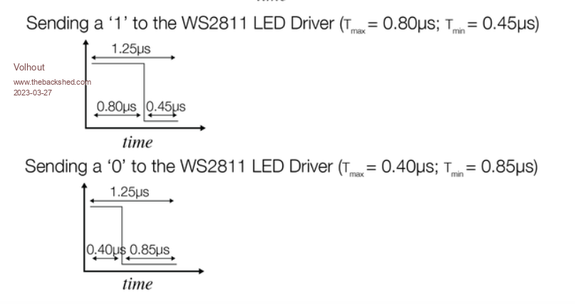
Hoi Nick, R3 en R4 moeten misschien wat kleiner in waarde. De signalen naar de WS2812 zijn timing critisch.  Volhout PicomiteVGA PETSCII ROBOTS |
||||
| Mixtel90 Guru Joined: 05/10/2019 Location: United KingdomPosts: 6814 |
Ah - I assumed it was a single LED, not an array. The system I suggested allows the output from the first LED to drive the input of the next, but you should keep the power rails separate. The output signal is within acceptable range of one powered from 5V. Mick Zilog Inside! nascom.info for Nascom & Gemini Preliminary MMBasic docs & my PCB designs |
||||