|

|
Forum Index : Microcontroller and PC projects : Take care experimenting with a Raspberry Pico
| Page 1 of 2 |
|||||
| Author | Message | ||||
| nbrok Regular Member Joined: 13/02/2023 Location: NetherlandsPosts: 60 |
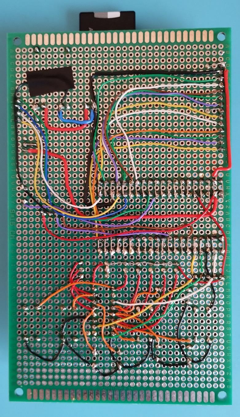
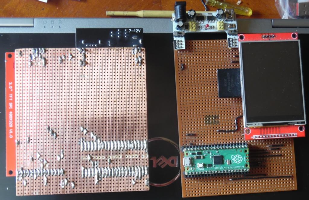
Hi, I had a déjà vu experimenting with the pico and a spi display with touch screen. It didn't work as expected. Why? I didn't held me at the HF rules I learned as Ham-radio amateur. The spi is working at 25 MHz and with long thin wires you generate several noise problems on the spi bus. The power (3V) gives a smaller noise ratio then at 5V and amplifies the problem. On a designed PCB the problem doesn't occur because of the copper-pour shielding. The problem was the gui test lcdpanel command. It shows moving circles and generates a lot of SPI traffic. The first minute all seems working fine, but after that the display flashes white and doesn't recognize any command until the Pico is reset or power down upped. This far I only experimented with microcontrollers lower than 35 MHz clock and 400 KHz spi bus. So simply soldering a pico with wires on a experimenters PCB can generate a lot of problems  Then I see a contribution from Tom with his Pico bintendo. Nice photos but he doesn't show his wire side.  . I'm curious how he did it. . I'm curious how he did it.Edited 2023-03-27 15:59 by nbrok Greetings, Nick de pe1goo |
||||
| Volhout Guru Joined: 05/03/2018 Location: NetherlandsPosts: 4256 |
Hi Nick, I did not check recently, but I recall SPI worked at 16MHz. Maybe the speed was increased for faster drawing on LCD. But for a "shared" SPI bus (SD card, touch, LCD) 25MHz is quite high. That definitely needs carefull design and routing. Good observation ! Thanks. Volhout Edited 2023-03-27 16:23 by Volhout PicomiteVGA PETSCII ROBOTS |
||||
| Mixtel90 Guru Joined: 05/10/2019 Location: United KingdomPosts: 6814 |
The main problem is breadboards. They aren't a good thing once you get over a few MHz as there is a lot of capacitance between the rows of sockets. Also, most people (and I'm one of them!) will insist on using Dupont connectors in breadboards and most are not suitable to accept them as the springs are too small and too weak. They are only intended for bare wire connections. You may get away with Dupont connectors for a while, but they do shorten the life of the breadboard. Even worse are male header pins with a square cross-section. These are also commonly used and *will* kill the breadboard in a relatively short length of time, particularly if it's a cheap Chinese one. Having said all that, I've often run SPI LCD displays plugged into breadboards together with SD cards. It may be naughty but it does seem to work. :) Mick Zilog Inside! nascom.info for Nascom & Gemini Preliminary MMBasic docs & my PCB designs |
||||
| thwill Guru Joined: 16/09/2019 Location: United KingdomPosts: 4047 |
Let's start with an obligatory "Not a Guru", I know nothing about electronic engineering in general or interference between signals specifically. The PicoGAME LCD / Bintendo Tomboy is a complete lash-up without even the basic bypass/decoupling capacitors (except what is already present on the Pico and LiPo charging modules). This *may* explain the audio noise problems I am encountering  . .I'm fairly certain I have posted this (now slightly out of date) photo before:  Note that the insulation tape is purely structural. Beginner's luck ... or it's not that hard after all and some of the capacitor / routing voodoo, at least for hobby projects, is just superstition ? I'd be looking for an unidentified firmware bug, try paring down your program to a bare minimum that display the symptoms. Best wishes, Tom Edited 2023-03-27 19:11 by thwill Game*Mite, CMM2 Welcome Tape, Creaky old text adventures |
||||
| nbrok Regular Member Joined: 13/02/2023 Location: NetherlandsPosts: 60 |
Hi Tom, First, you use thicker wires I see (I used wirewrap wires). Second, your layout is so that your wires aren't that long (at 25MHz can that make the difference). Also you can be lucky with the version of TFT you use. In my test three of the four I had didn't like the noise  . On my definitive PCB design I have no problems at all, what I already mentioned. . On my definitive PCB design I have no problems at all, what I already mentioned.So you where lucky, but for a beginner in electronics your work isn't that bad. Originally I'm an electronic engineer. In the eighties I repaired Floppy drives and measurement equipment. But thanks for showing your work. I was testing my schematic with breadboard type soldering, but with 25 MHZ you get a lot of problems  . .Edited 2023-03-27 20:37 by nbrok Greetings, Nick de pe1goo |
||||
| thwill Guru Joined: 16/09/2019 Location: United KingdomPosts: 4047 |
Hi @nbrok, Most of them are 30 AWG, I thought that was wirewrap wire ? I looked into wirewrap as an actual prototyping technique but the posts seemed to be expensive / difficult to come by. Likewise I've played with using wire with "solderable" insulation but found that it was not as solderable as it claimed to be. In the end I've settled on the approach shown whilst recognising it is a bit amateur. Some of the power and ground wires are 23 AWG "hookup" wire, used more out of superstition than knowledge that thicker wire would be better. Best wishes, Tom Game*Mite, CMM2 Welcome Tape, Creaky old text adventures |
||||
| Mixtel90 Guru Joined: 05/10/2019 Location: United KingdomPosts: 6814 |
Just don't tell the electrons. As long as they don't know what the wire is they won't care. They are very un-fussy creatures. Your wiring looks fine to me, Tom. I'm surprised that you're having problems, Nick. I'll be even more surprised if it turns out to be a wiring issue unless you've done something like bundling the wires together with a cable tie. Even at the speeds we have here I don't know of anyone that has hit that sort of a problem. Check your power supply first. These things will even work on strip board, with no ground plane. Just keep the wiring reasonably short. Mick Zilog Inside! nascom.info for Nascom & Gemini Preliminary MMBasic docs & my PCB designs |
||||
| Pluto Guru Joined: 09/06/2017 Location: FinlandPosts: 359 |
I am mostly using wires for my LCDs (20-30cm long soft silicon wires). Have not noticed any specific problems...except sometimes conneting to wrong pins. |
||||
| stanleyella Guru Joined: 25/06/2022 Location: United KingdomPosts: 2134 |
I've had no problems with spi touch lcd with sd card on strip board, maybe lucky.  |
||||
| matherp Guru Joined: 11/12/2012 Location: United KingdomPosts: 9139 |
That is much nicer wiring than using flying leads and effectively not much different than a PCB. The only change I would make is to cut all the LCD tracks as close to the connecting wires as possible so there is the minimum track with the signals on them |
||||
| nbrok Regular Member Joined: 13/02/2023 Location: NetherlandsPosts: 60 |
Thanks for your encouraging replies. What EEJIT did is close to a PCB. I can tell you that when there is a problem with hardware then it will certainly appear to me...  in other words: if it works for me then it works for anyone or is everyone correcter English?. in other words: if it works for me then it works for anyone or is everyone correcter English?.  Another problem that occurs sometimes, fortunately rarely, is a power on reset problem of the SD-card. Then I get Error: There is no valid FAT volume when accessing the sd card. (first drive "b:" then i.e. files...) I can live with this: power down and on again solves it. I read also that the internal 3.3V powersupply can produce a lot of noise and some suggest to switch this of and use a linear voltage regulator in stead....  I'll do some further experiments but I'm a little disappointed in the design of the raspberry pico. I mean it not as worse as it sounds  Greetings, Nick de pe1goo |
||||
| Mixtel90 Guru Joined: 05/10/2019 Location: United KingdomPosts: 6814 |
Power-on reset of the SD card seems to depend on the card! Peter always filters its supply with 2R2 and 10uF (or more). That can cure all sorts of SD card problems that we've seen with standard SD cards. Micro SD cards seem to be much more forgiving. The switcher power supply on the Pico is actually an excellent performer, it's just got a lot of switching noise (like all switching power supplies do). If you aren't looking for the best performance from the ADC and aren't too bothered about hiss on the audio then leave it running. The main failings of the RP2040 are: There are silicon errors in the ADC and no workaround so the maximum resolution is about 8 bits. The maximum allowable source/sink current for the IOs is only 50mA in total. These apply to all RP2040 boards, not just the Pico. You get what you pay for. Actually, you probably get a lot more than you pay for when you see what it can do. :) Mick Zilog Inside! nascom.info for Nascom & Gemini Preliminary MMBasic docs & my PCB designs |
||||
| stanleyella Guru Joined: 25/06/2022 Location: United KingdomPosts: 2134 |
I will cut the unused tracks as the capacitance between tracks could cause problems. There's "vero" that looks like bread board but it costs more. Great for transferring bread board to something more reliable. I find bread board tracks too short ie not enough holes per track. I never got problems with bread board ...as long as you don't move it :) "vero" has been around ages but I can't find a "spot face cutter" so use drill bits to cut tracks. There's a pc vero designer, Veecad but it was easier to use pen and paper. You can't use vero for a vga connector. |
||||
| Mixtel90 Guru Joined: 05/10/2019 Location: United KingdomPosts: 6814 |
Stripboard cutter here. Mick Zilog Inside! nascom.info for Nascom & Gemini Preliminary MMBasic docs & my PCB designs |
||||
| stanleyella Guru Joined: 25/06/2022 Location: United KingdomPosts: 2134 |
If using ili9341 and ili9488 with built in sd card reader and running the displays from 5V linear reg the sd card supply is from the lcd. seems ok. pico runs from 3.3V linear reg with 3.3V enable grounded. even ili9488 with touch miso and sd card miso joined and display miso joined with 580R works ok. There was a problem before but it seems stable with the resistor. using kingston and lexar micro sd cards. |
||||
| stanleyella Guru Joined: 25/06/2022 Location: United KingdomPosts: 2134 |
cheap. Farnell same but postage. I'll stick with bits in a chuck for now. cheers. |
||||
| Mixtel90 Guru Joined: 05/10/2019 Location: United KingdomPosts: 6814 |
Bitsbox postage is cheap - and it doesn't matter how big your order is. Useful source of bits and they are quick delivery. Mick Zilog Inside! nascom.info for Nascom & Gemini Preliminary MMBasic docs & my PCB designs |
||||
| stanleyella Guru Joined: 25/06/2022 Location: United KingdomPosts: 2134 |
They don't do 4.7mH inductors. I got off ebay, 10 for £1.95 |
||||
| Mixtel90 Guru Joined: 05/10/2019 Location: United KingdomPosts: 6814 |
So did I. :) Bitsbox don't have a huge range but they are pretty good. They are only a small company.No minimum quantities or minimum order values either. Mick Zilog Inside! nascom.info for Nascom & Gemini Preliminary MMBasic docs & my PCB designs |
||||
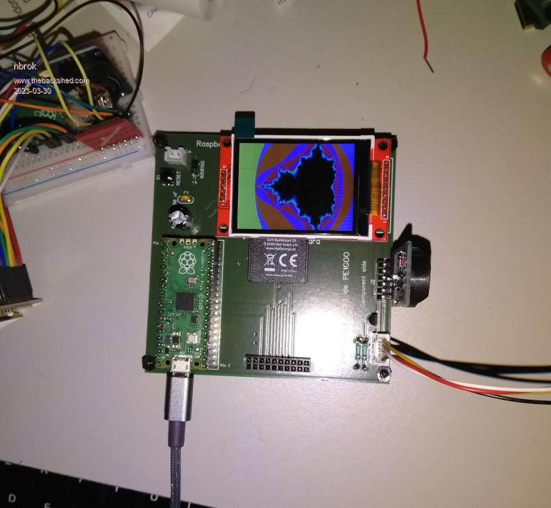
| nbrok Regular Member Joined: 13/02/2023 Location: NetherlandsPosts: 60 |
Hi, I just received my last pcb design from Aisler PCB service and here I have no problems with the LCD. Here a photo:  Edited 2023-03-30 01:34 by nbrok Greetings, Nick de pe1goo |
||||
| Page 1 of 2 |
|||||