Notice. New forum software under development. It's going to miss a few functions and look a bit ugly for a while, but I'm working on it full time now as the old forum was too unstable. Couple days, all good. If you notice any issues, please contact me.
Mixtel90 Guru Joined: 05/10/2019 Location: United KingdomPosts: 9136
Posted: 02:21pm 19 Aug 2026
Copy link to clipboard
Print this post
Yay! I think I've managed to modify my PC3x (well, it needed some sort of a name - it'll be PC3x WS) board for the CORE2350B. The point to point checks are OK and nothing of consequence on the DRC.
Waveshare swapped some pins around on the controls side but, worse than that, they reversed even and odd numbered pins on the opposite side. It's really quite a bit off "compatible" even if it looks similar.
Mixtel90 Guru Joined: 05/10/2019 Location: United KingdomPosts: 9136
Posted: 03:58pm 19 Aug 2026
Copy link to clipboard
Print this post
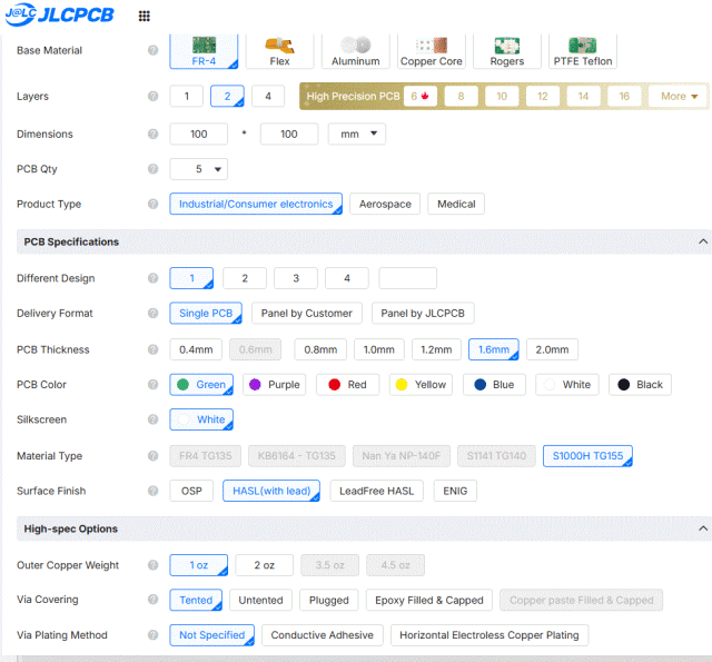
@lizby I've just tried uploading the board to JLCPCB and it put a "Materials charge" on for me too. I did wonder if it's because I've used smaller vias than I usually do. I can't think of anything else that's changed. The size isn't the problem, they seem to allow up to 102mm square for the cheap price.
It makes quite a difference to the final price - in the wrong direction. :(Mick
matherp Guru Joined: 11/12/2012 Location: United KingdomPosts: 11881
Posted: 04:03pm 19 Aug 2026
Copy link to clipboard
Print this post
Mick the smallest I use are 24mil/12mil and they never get surcharged
Mixtel90 Guru Joined: 05/10/2019 Location: United KingdomPosts: 9136
Posted: 04:36pm 19 Aug 2026
Copy link to clipboard
Print this post
I increased the via holes from 0.4mm to 0.5mm and uploaded again. It came up with a different price so I ordered the cheaper one. :) Neither of the prices in the basket was as expensive as it would have been based on the quote. Weird.
These are the gerbers with the bigger holes: PC3x-2.zipMick
Mixtel90 Guru Joined: 05/10/2019 Location: United KingdomPosts: 9136
Posted: 05:25pm 19 Aug 2026
Copy link to clipboard
Print this post
This is the gerber set for the Waveshare CORE2350B module on the PC3x WS. Everything else is the same as for the PGA2350B so you can use the circuit diagram and BOM (with the obvious change) for that. I've used the bigger via holes just in case it made a difference to the cost - it shouldn't have.
javavi Guru Joined: 01/10/2023 Location: UkrainePosts: 609
Posted: 05:43pm 19 Aug 2026
Copy link to clipboard
Print this post
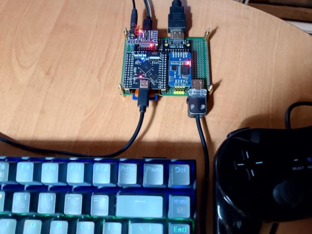
Meanwhile, I attached a Wii game controller connector to my breadboard. I don't know how popular it is here, but I'm using it.
I'd also be interested in user opinions on which PС3 port pins are best for connecting two three-wire NES/SNES gamepads?
Mixtel90 Guru Joined: 05/10/2019 Location: United KingdomPosts: 9136
Posted: 05:49pm 19 Aug 2026
Copy link to clipboard
Print this post
The NES/SNES gamepads are simple clock/data/latch signals and are completely software driven. You can use any pins except GP20/GP21 which are used for system I2C.Mick
lizby Guru Joined: 17/05/2016 Location: United StatesPosts: 3881
Posted: 05:53pm 19 Aug 2026
Copy link to clipboard
Print this post
I didn't change anything in the selections. 1.6mm in green is selected. FR4 is grayed out and S1000H was pre-selected. All other "Material" options are grayed out. That's probably it--I'll ask why.
lizby Guru Joined: 17/05/2016 Location: United StatesPosts: 3881
Posted: 06:22pm 19 Aug 2026
Copy link to clipboard
Print this post
Chat with JLC also asked me about the hole size and then for the gerber files, which I uploaded. He then suggested I upload again. I uploaded the latest set and still got the higher base price and the $11 Material Type charge.
Mixtel90 Guru Joined: 05/10/2019 Location: United KingdomPosts: 9136
Posted: 06:31pm 19 Aug 2026
Copy link to clipboard
Print this post
Odd. TBH I'm not sure which is which in my basket as both show minimum hole size as 0.3/0.4mm when I know that for the second upload it's 0.5mm! Consequently I'm not sure which was the cheaper one, but that's what I ordered. It was the usual special offer price that I usually pay.
Unfortunately SL6 has no concept of vias - they are merely PTH pads. You opt to let the solder mask cover them individually. Consequently special arrangements or settings for vias don't make sense.Mick
Mixtel90 Guru Joined: 05/10/2019 Location: United KingdomPosts: 9136
Posted: 12:18pm 02 Sep 2026
Copy link to clipboard
Print this post
I've been waiting for my PC3x boards for ages, but they finally seem to be in the country now. :) JLCPCB produced them on time and they got to the airport in Hong Kong. They left the airport then there's been a delay of about 4 days before they got to London. I suspect they were using a Sopwith Camel for the delivery... On top of that the transport companies web site was slower than an ant in treacle then didn't recognize the shipping number. I've had better experiences.Mick
Mixtel90 Guru Joined: 05/10/2019 Location: United KingdomPosts: 9136
Posted: 02:49pm 03 Sep 2026
Copy link to clipboard
Print this post
PCBs have just turned up! Evri strikes again... Put package down (not in "safe place" where requested), ring doorbell and run away as quickly as possible.
They *look* ok. Now to build one up and see if it works anything like a PC3. I've not got a RM2 for the prototype as it might be a pain to remove if I have to strip the board down because it's rubbish.
I've been designing some front and rear panels today. Just in case it works. :)Mick
Mixtel90 Guru Joined: 05/10/2019 Location: United KingdomPosts: 9136
Posted: 09:02am 04 Sep 2026
Copy link to clipboard
Print this post
Hmmm... I ordered micro USB breakout boards on the basis of the advertising (from AE of course. TLZWLA). The advert shows photos of a board 14.3mm wide x 15.2mm deep and a drawing (actually 7 pin rather than 5) of a board 13mm wide x 14mm deep! However, they were about 82p for 10 so I thought I'd compromise a bit on the layout and take a chance. :)
What they sent is 15mm wide x 14mm deep and doesn't correspond with either the photos or the drawing. It will *just* fit if it's persuaded with a file down both sides. Precision engineering, folks!
However, a dry fit test, after a bit of filing, gets all the bits in where they are supposed to be. Which is something of a relief. :)Mick
Mixtel90 Guru Joined: 05/10/2019 Location: United KingdomPosts: 9136
Posted: 09:02am 06 Sep 2026
Copy link to clipboard
Print this post
Oh dear. I hadn't spotted that. You can't plug the RTC in with the battery on top if you want to use the RM2015S enclosure. Options: 1) Use the RM2015M, which is easier to get but 50mm high. Price difference isn't much. 2) Solder the RTC module pins to the PCB without the sockets. Makes it very difficult to remove in future. 3) Remove the battery holder from the module and mount it off-board. There is plenty of space at the LH side of the box to stand it on its side, away from the RM2. I think it's possible to use double sided sticky to fasten it to a USB socket. I like this option.
================================ PC3x UPDATE
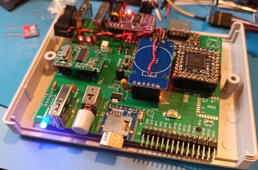
Some of it's working with beta 2 now. SD card isn't yet, no idea why not. Audio is currently in progress - I'm trying to blob those horrible pads. RTC isn't keeping time yet because I've taken the battery holder off. USB seems to be fine with this wireless keyboard.
Installation using OPTION RESET PICO COMPUTER 3 worked first time. All I've needed to change was to change the keyboard to a proper one. ;)
The electrolytic caps are missing, as are the reset button and the USB fuse. All on order from Bitsbox so I'm not waiting for AE. I've no angled pins for the GPIO port yet either - they don't stock them.
================================= SD card now working, woth 6.03.00 firmware. I've not done anything else other than change that and solder in the connector for the GPIO (I had enough 5-way that I bought for Elemento boards).
Audio is no use. Very loud and hopelessly distorted. No response to PLAY VOLUME. The links on the pads look right to me. .
========================= We have audio. :) Back to the SD card. I has voltage (rather low though) and the pins have continuity to the PGA top-side pins. Input voltage to the LDO is on the low side, output is therefore low and the output cal and SD card filter cap are both missing. It may have to wait until the new bits arrive.
Mixtel90 Guru Joined: 05/10/2019 Location: United KingdomPosts: 9136
Posted: 08:13am 07 Sep 2026
Copy link to clipboard
Print this post
Pity about the audio. The 4 audio pins are floating, only used for mechanical support. I tested it from the jack output into 64R phones and a headphone amp (which I assume might be high impedance but I don't know). It could be that it feeds directly into a preamp stage.
One USB is missing here as I want access to the LED to sort out it's final height on the front panel.
I think the two ruby red LEDs are very old. We got them for a job at work but they didn't get used so I liberated them from the drawer when I left as the control panels section had already shut down then, they would only have got tipped in the bin.
HDMI is working, but the picture "blinks off" now and again. I think that's yet another of this monitor's problems = it doesn't like having both it's inputs connected!Mick
matherp Guru Joined: 11/12/2012 Location: United KingdomPosts: 11881
Posted: 08:28am 07 Sep 2026
Copy link to clipboard
Print this post
check https://www.makerguides.com/playing-audio-with-esp32-and-pcm5102/#Function_Jumpers for the audio config. I think this is correct but I don't have one I have configured with me, can confirm Monday
Mixtel90 Guru Joined: 05/10/2019 Location: United KingdomPosts: 9136
Posted: 08:44am 07 Sep 2026
Copy link to clipboard
Print this post
Thanks, Peter. Just checking it out now.
Officially the chip is 1K min load on each channel, but the module already has 470R so I expected at least something reasonable on the phones. Output is stated as 2V p-p around zero so I also expected it to be loud, but not uncontrollable.
================================= EDIT All sorted! I had a bad solder blob. It had lifted the centre pad. A wire link fixed it. May this be a warning - to get good blobs drop the iron temperature to about 250C. :)
So, things to watch out for if you are interested in this design: Be aware that the micro SD breakout board might be advertised as something different! The GND pins on the USB=A sockets aren't connected on version 1.0 of the pcb! (There is a story behind this.) However they are easy enough to link to one of the shell pads. Unless you take the battery holder off the module you can't use the RM2015S case.
ville56 Guru Joined: 08/06/2022 Location: AustriaPosts: 612
Posted: 09:19am 07 Sep 2026
Copy link to clipboard
Print this post
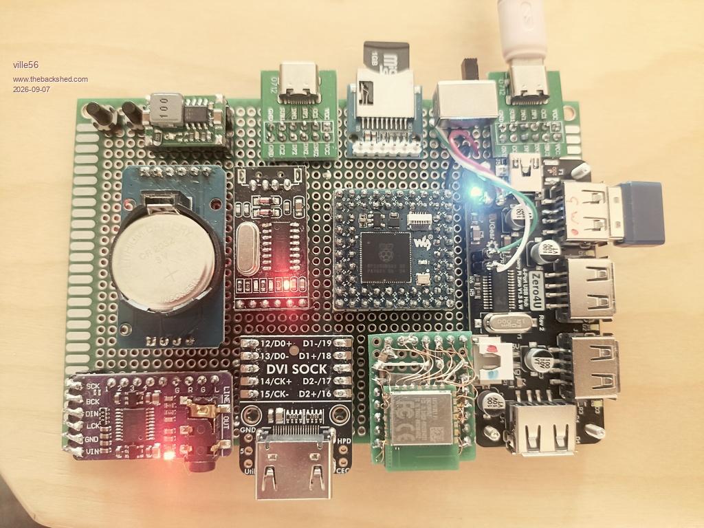
it's ugly but it works ... even the WIFI "adapter" is working. The backside wiring is a rats nest with attention to the ground wiring. What is still missing is the 30 pin connetor for the IO pins. Will follow as soon as I'm able to "see" again. The wiring on the backside was a real strain to my eyes as my 3D vision slowly becomes very bad.
There is one minor problem left as the HDMI 800x600 has a lot of jitter on the image, all other resolutions do work fine. May be the monitor though.
Edit: It's definitely the monitor and it is with option resolution 720 only, strange ... Edited 2026-09-07 20:01 by ville56 73 de OE1HGA, Gerald
Mixtel90 Guru Joined: 05/10/2019 Location: United KingdomPosts: 9136
Posted: 10:46am 07 Sep 2026
Copy link to clipboard
Print this post
It looks nice from the top though. Who looks underneath? :) Even better if it works! I love your wifi module. :) No wonder your eyes get kn....d. lol
Mine is the way it is specifically because I wanted it to fit into the same case. No other reason, other than as a challenge.
========================================
I've decided to redo the gerbers for PC3x. They'll be a day or two and I'll sort out the ones for the front and rear panels too. Edited 2026-09-08 04:32 by Mixtel90Mick
Mixtel90 Guru Joined: 05/10/2019 Location: United KingdomPosts: 9136
Posted: 09:24am 12 Sep 2026
Copy link to clipboard
Print this post
PC3x hasn't gone to sleep. It's just taking a little longer than I anticipated. I've made more improvements than I intended, including getting rid of some SMD components and adding a lot to the manual.
The latest "maybe" is rearranging the rear panel. I'm not happy with the jack on the I2S module for a cased design. It's too likely to cause mechanical problems as there is insufficient support if the module is plugged in. My latest idea is to turn it upside down, which already helps a lot, and to fit a support pillar behind the module to take some of the stress when inserting the plug. That means also moving the console and prog connectors. Now, I have managed to do all this but now you will probably have to unplug the audio jack to use the prog connector - not really a serious problem, I don't think. Of course, this screws up the gerbers (which I've already produced 3 times so far) for both PC3x versions and the rear panel. :) I'm just making my mind up whether to implement this as described or look for a different way.

 Notice. New forum software under development. It's going to miss a few functions and look a bit ugly for a while, but I'm working on it full time now as the old forum was too unstable. Couple days, all good. If you notice any issues, please contact me.


 Print this post