Notice. New forum software under development. It's going to miss a few functions and look a bit ugly for a while, but I'm working on it full time now as the old forum was too unstable. Couple days, all good. If you notice any issues, please contact me.
strangepapyrus Newbie Joined: 24/06/2025 Location: United KingdomPosts: 2
Posted: 11:43am 21 Jun 2026
Copy link to clipboard
Print this post
Hi,
Electronics is a fairly new hobby for me and this is my first post here. Please could anyone offer some advice to help me out? Thank you.
I decided to have a go a building the Picomite VGA and have been partially successful.
I ordered the PCBs to the UK from JLCPCB and the other parts sourced from various suppliers.
The VGA works, but not the keyboard. I have 5 volts out from the port so the MOSFET level shifting circuit must at least be partially working? The system boots, I can see all the post boot info on screen and a cursor, but absolutely nothing from the keyboard.
Thinking I must of done something wrong somewhere, I had a second board, so built a second picomite from scratch, including a second pico ....... and exactly the same. There does not seem to be power to the keyboards, apart from an initial flash of the leds on my Fujitsu keyboard at boot, CAPS LOCK, does not illuminate when pressed for example, and no output onscreen.
I have tried different keyboards. I have newer Fujitsu keyboards (x2) and an older Compaq keyboard (x1) - all PS2 wired, no adapters. I have tried soldering on different PS2 ports and different MOSFETS from different suppliers. I've tested the resistors and all seem good. I've tested the output from the PS2 port. I've tried newer and older firmwares. I've swapped the picos around and all to no avail.
The power supply is one I used to use on a raspberry pi, 5V 3000mA output.
I am starting to lean towards the PCBs being bad as I'm a bit stuck as to what's going on, so if anyone could offer any advice I'd be extremely grateful.
Thanks, Martin
matherp Guru Joined: 11/12/2012 Location: United KingdomPosts: 11516
Posted: 11:49am 21 Jun 2026
Copy link to clipboard
Print this post
What firmware version are you using? Before anything else type "OPTION RESET VGA DESIGN 1" and then try again.
robert.rozee Guru Joined: 31/12/2012 Location: New ZealandPosts: 2529
Posted: 12:05pm 21 Jun 2026
Copy link to clipboard
Print this post
hi Martin, welcome to the forums.
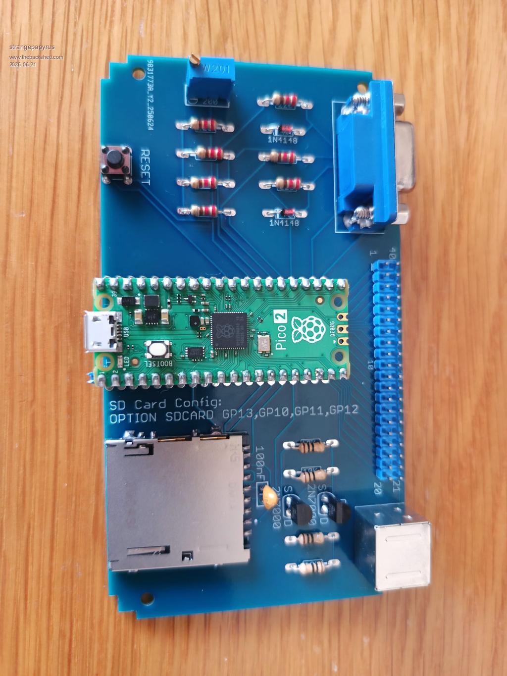
what are the colour bands on the four resistors near the 2N7000 transistors? from the photo they appear to be brown-black-black-gold, which would indicate a value of 10 ohms each. they should be 10,000 ohms each, which are instead coded as brown-black-orange-gold (the gold indicates 5% tolerance parts, which is unimportant).
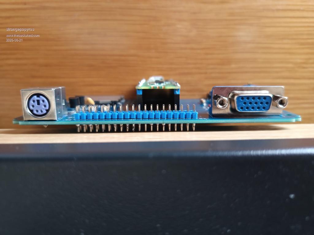
you do appear to have inserted the 40-pin blue header (located between the keyboard and VGA sockets) with the long ends of the pins the wrong way round, but this does not matter too much at the moment. otherwise, you have done a very nice job of the assembly and soldering
cheers, rob :-) Edited 2026-06-21 22:15 by robert.rozee
phil99 Guru Joined: 11/02/2018 Location: AustraliaPosts: 3293
Posted: 12:33pm 21 Jun 2026
Copy link to clipboard
Print this post
Rather than trying to de-solder the entire header it may be possible to push the pins through one at a time. With the board upside down on a firm surface re-melt the solder and press down to 1mm above the PCB. The blunt end of a skewer, or better still a carpenters panel-pin punch should do the job.
As Rob said they do look like 10Ω resistors. If so that could damage the Pico if powered up for long. I think Peter has set 8mA current limits for the pins but it will still be heating the chip.
strangepapyrus Newbie Joined: 24/06/2025 Location: United KingdomPosts: 2
Posted: 03:08pm 21 Jun 2026
Copy link to clipboard
Print this post
Oh my goodness. What a plonker. I need better glasses and missed that K in the list of parts in the design construction notes.
I have indeed put 10 rather than 10,000 ohm resistors in!
Thank you all so much for the help and suggestions. I really appreciate it.
Sometimes forums aren't very kind to noobs, so thanks for not being like that.
I'll get some of the right resistors in and get back to you with hopefully some success!