|

|
Forum Index : Microcontroller and PC projects : RP2350B 64 Pin development board
| Author | Message | ||||
| circuit Senior Member Joined: 10/01/2016 Location: United KingdomPosts: 245 |
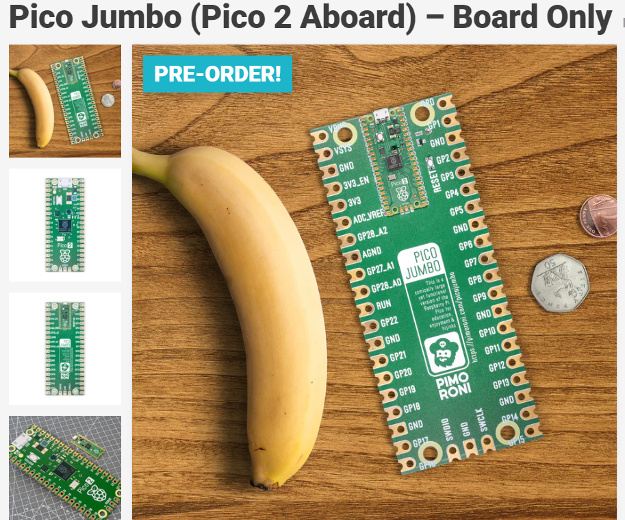
I greet with delight the introduction of the 64 pin RP2350B and the port of MicroMite Basic to this chip. Peter, my gratitude for, and deep appreciation of, your most selfless work on these projects is without bounds. The only current embodiment of the 64pin version that I can find is the Pimoroni PGA2350; a board that I find rather absurd. It is hardly a development friendly outline. What I would really welcome (and I assume would any others who work with stripboards and breadboards in their development projects) would be an RP2350B mounted on a straightforward long board with 32 pins on each side in the manner of the now obsolete MX795 board by Sparkfun. I have several of the Sparkfun boards and, despite the version of MMBasic for the board having had no development for several years, I find the layout so compelling that I continue to use them from time to time. The picture below shows a Pimoroni PGA2350 board next to the MX795 board; given a choice, which format would YOU prefer to play with? So here is a call to manufacturers or to those with contact to them, perhaps Sparkfun or Pimoroni, to mount up an RP2350 on a board in the format of the MX795 (UBW32) board. I am sure that this would sell rather well! (I would be first in the queue.) Edited 2024-08-24 23:55 by circuit |
||||
| Mixtel90 Guru Joined: 05/10/2019 Location: United KingdomPosts: 6779 |
The problem is, what would it cost? The PGA2350 is £9 here. The cost of 5 custom made PCBs is less than £9, so total cost for one is £18. You can then get another 4 identical builds for £9 each if you just buy more PGA2350 modules. The MX795 is about $50 each - almost three times the price of one PGA2350 setup. I'll bear this in mind for a future project. Edited 2024-08-25 00:27 by Mixtel90 Mick Zilog Inside! nascom.info for Nascom & Gemini Preliminary MMBasic docs & my PCB designs |
||||
| PhenixRising Guru Joined: 07/11/2023 Location: United KingdomPosts: 857 |
 Who knows...might be another version due  |
||||
| Mixtel90 Guru Joined: 05/10/2019 Location: United KingdomPosts: 6779 |
I saw that. It's nice! You can connect to it using crocodile clips. :) It's quite feasible to make a breadboard friendly version of the RP2350B, but it's seriously ungainly and fragile with all those pins (a minimum of 64). You also have to ask, why? The Pico 2 makes an excellent breadboard tor testing out conceptual ideas for the RP2350, even if it hasn't got all the IO pins. After that, why not use a custom PCB for the final build? Mick Zilog Inside! nascom.info for Nascom & Gemini Preliminary MMBasic docs & my PCB designs |
||||
| robert.rozee Guru Joined: 31/12/2012 Location: New ZealandPosts: 2350 |
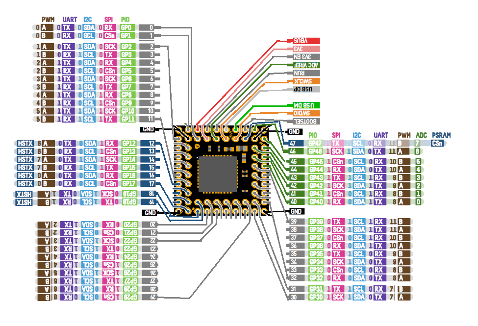
the 80-pin package only has 48 GPIO pins, including the 8 that have alternative functions as ADC inputs. plus you would want 3v3, ground, RESET, and for fun lets also include DP and DM (the two USB signals). also an onboard LDO regulator capable of handing up to 12 supply would be handy - rounding it out to an even 52 pins in total. onboard it would make sense to have the SPI flash, a USB socket for uploading the firmware (this necessitates a regulator capable of taking the 5v USB supply down to 3v3). and why not also an HDMI socket and header to plug in one of those little microSD socket daughterboards? if we subtract out the 8 GPIO pins for HDMI, and the 4 GPIO pins that we will use for the SD card interface (via a 6-pin header), that takes our 52 back down to... just 40 pins. this is no more than the existing pico PCB, a decidedly non-fragile number. and to accommodate the width of the HDMI socket, we can widen the PCB by an extra 0.2". cheers, rob :-) |
||||
| JohnS Guru Joined: 18/11/2011 Location: United KingdomPosts: 3800 |
Maybe waveshare will make a board (a bit like the Sparkfun/UBW32) using the 64-pin RP2350 or maybe jlcpcb will assemble such chips onto any design (Mick?) - if/when they get the parts? John |
||||
| Mixtel90 Guru Joined: 05/10/2019 Location: United KingdomPosts: 6779 |
JLCPCB will no doubt make anything within reason, but the chips definitely won't be available to them while there is a big demand for them for the Pico 2 at least. I still ask Why? though. There's no point. Apart from access to the QSPI bus the Pico 2 has just about everything that the bigger chip has, just less IO. It's fine as a design & development platform. If you absolutely *must* have all the IO then have an expansion board for a PGA2350 with the necessary bits mounted on it. Then there's that promised XL stamp module from Soldering Party. That could go onto a carrier board with 0.1" spacing. Probably... Mick Zilog Inside! nascom.info for Nascom & Gemini Preliminary MMBasic docs & my PCB designs |
||||
| Volhout Guru Joined: 05/03/2018 Location: NetherlandsPosts: 4223 |
Don’t forget the crystal….. Volhout PicomiteVGA PETSCII ROBOTS |
||||
| Mixtel90 Guru Joined: 05/10/2019 Location: United KingdomPosts: 6779 |
I really don't like the idea of restricting the IO pins by putting stuff on-board that really shouldn't be there because you can't switch it off or ignore it and use those pins. That's been done in the past and it feels like it's crippling the system. If you want a crippled system to experiment with then you already have it - the Pico 2. If you want a full bells and whistles system then you still have to wait - the PGA2350 isn't quite there as the QSPI bus isn't exposed on the pins (or on pads AFAIK, I've never seen underneath one). Anyway - it needs someone proficient in using multi-layer boards and SMD to sort something like you're talking about, Rob. I'm the wrong bloke for that. :) Mick Zilog Inside! nascom.info for Nascom & Gemini Preliminary MMBasic docs & my PCB designs |
||||
TassyJim Guru Joined: 07/08/2011 Location: AustraliaPosts: 6097 |
My board will be a Pimoroni PGA2350 perched on some stripboard.  I need to add some gnd lines to allow for the run and boot buttons and rearrange the USB pins to suit my breakout board but you get the idea. My PGA modules will arrive this week... Jim Edited 2024-08-25 14:43 by TassyJim VK7JH MMedit MMBasic Help |
||||
| phil99 Guru Joined: 11/02/2018 Location: AustraliaPosts: 2135 |
A breadboard adapter for the PGA2350. Could be a PCB or stripboard with a lot of wire links.  It should work well with Jim's layout above by extending the wires from the second header strip to the opposite end of the board. . Edited 2024-08-25 15:26 by phil99 |
||||
| Mixtel90 Guru Joined: 05/10/2019 Location: United KingdomPosts: 6779 |
The PGA2350 is an interesting beast to lay out a PCB around. :) It took me a couple of false starts to get going, including scrapping an almost completed design because things were just getting in the way too much. Mick Zilog Inside! nascom.info for Nascom & Gemini Preliminary MMBasic docs & my PCB designs |
||||