|

|
Forum Index : Microcontroller and PC projects : RP2350 hardware - Mixtel 90
| Author | Message | ||||
| Mixtel90 Guru Joined: 05/10/2019 Location: United KingdomPosts: 6778 |
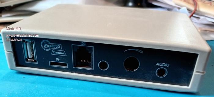
Gamma is here - this is the SMD version. circuit.pdf manual.pdf gerbers-PCB-G.zip gerbers-plates-G.zip NOTE: If ordering from JLCPCB make sure that you get the board thicknesses right. The PCB is 1.2mm and the panels are 1.6mm. I've put the order number string on the backs of the boards so if you set that option you won't see them. I now have a set of boards on order, in a fetching purple with black panels. I'm feeling a bit Goth today. :) I *think* the manual is right now. It's been a bit of a hurried editing session today. . Edited 2024-09-14 06:19 by Mixtel90 Mick Zilog Inside! nascom.info for Nascom & Gemini Preliminary MMBasic docs & my PCB designs |
||||
| javavi Senior Member Joined: 01/10/2023 Location: UkrainePosts: 206 |
Thanks Mick! Very interesting component design PCB. |
||||
| Mixtel90 Guru Joined: 05/10/2019 Location: United KingdomPosts: 6778 |
I'll sort out the version with the Adafruit breakout board shortly. Unfortunately that one will be offered with no guarantee that it will fit as the Adafruit mechanical data is insufficient. I think there's an Eagle file but I can't read those. Mick Zilog Inside! nascom.info for Nascom & Gemini Preliminary MMBasic docs & my PCB designs |
||||
| Volhout Guru Joined: 05/03/2018 Location: NetherlandsPosts: 4222 |
Mick, Hdmi needs all 8 traces to be equal length. From chip to connector. Best within 1 or 2mm. That is why these pine are used on pico2, and the hdmi connector is default at at the short edge. That more or less forces equal trace length. Check your design, you may save yourself a lot of trouble. Volhout Edited 2024-09-15 23:53 by Volhout PicomiteVGA PETSCII ROBOTS |
||||
| Mixtel90 Guru Joined: 05/10/2019 Location: United KingdomPosts: 6778 |
All I can say is what I've found. I've had 720P running apparently rock solid on a TV using my Alpha board. You may very well be correct, but it's not what I personally have found by experiment. It could be what's causing the problem on my monitor but I've no way of checking that - and it may even by why it was being sold on ebay. If I have to stick with DVI because of some sort of irregularity that turns up on a more extreme test then so be it. I'll not be upset about it and I won't redesign this particular project. :) As far as I'm concerned it's virtually complete now. I don't think a modular design like this is possible with the Pico turned through 90 degrees. You can only do that when you have control over individual component placement, like Peter's design. You have to start leaving modules off in order to get anything like that. I don't want all the USB connectors on the front, including the Pico one. It's not what I was aiming for. I do want an accessible headphone socket and volume control - I've no interest in line output as I can't use any sort of speakers in the living room. ----------------- Edit Just tested with my lad's big TV and that appears to be fine in widescreen too. Perhaps the line mismatch at the Pico end is so severe that differences in trace length are swamped by 220R series resistors. ----------------- Another Edit Just tried the main living room TV. With widescreen off it complains that it's an unsupported resolution and I should adjust my PC. It seems to work in Mode 1 anyway. In widescreen the display flashes on and off regularly at about 1 sec intervals but it doesn't complain. . Edited 2024-09-16 01:36 by Mixtel90 Mick Zilog Inside! nascom.info for Nascom & Gemini Preliminary MMBasic docs & my PCB designs |
||||
| Mixtel90 Guru Joined: 05/10/2019 Location: United KingdomPosts: 6778 |
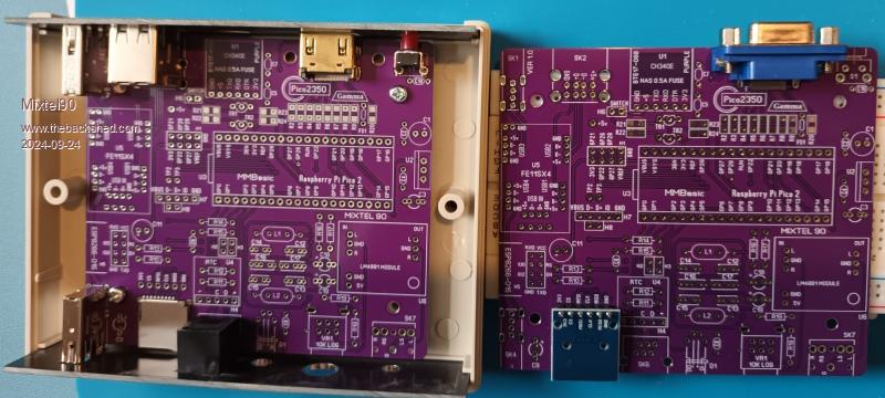
Well, I'll be able to test it soon. :)   The RH board shows the possibility of using a VGA connector and a micro SD module. I can't complete one of these yet as I'm still waiting for bits. As you can see though, a dry assembly run is looking promising at this stage. It was a great relief when the front and rear panels worked well (at this stage - I've not tried all the parts yet). A pair of front and rear panels cost appreciably more than the main PCB because they are longer than 100mm. It's mildly annoying. The rear panel is cut out for the HDMI connector. If someone wanted to use the VGA connector it would need a bit of work on their part. I don't intend to do a rear panel to fit it unless there's a demand. Mick Zilog Inside! nascom.info for Nascom & Gemini Preliminary MMBasic docs & my PCB designs |
||||
| Volhout Guru Joined: 05/03/2018 Location: NetherlandsPosts: 4222 |
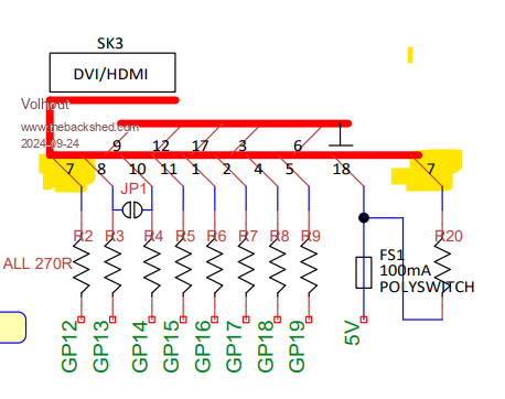
Hi Mick, Looks beautiful. I like the purple color. I hope this is no issue (see yellow highlight)  Volhout Edited 2024-09-24 21:27 by Volhout PicomiteVGA PETSCII ROBOTS |
||||
| Mixtel90 Guru Joined: 05/10/2019 Location: United KingdomPosts: 6778 |
My schematics aren't linked to the PCB design, unlike proper PCB software. That's a mis-trype and the RH one should be 17. :) Mick Zilog Inside! nascom.info for Nascom & Gemini Preliminary MMBasic docs & my PCB designs |
||||
| Mixtel90 Guru Joined: 05/10/2019 Location: United KingdomPosts: 6778 |
A couple of gotchas... 1: Be careful what you assume. The holes for the VGA connector pins were intended to be a simple hole with a pad on just the bottom side, and were, I thought, like that in SL6. However, because there is a pad on the bottom the hole becomes a THP so all those pads are connected to GND via the top ground plane! That gave me several shorts to GND on the HDMI pins as some signals are dual-purpose. It took me ages to find this. I thought solder had wicked up inside the HDMI connector at first, but the shorts were still there on a completely unsoldered board. 2: I thought I might leave the level shifter off, just link the MOSFETs out and then realized... RXD and TXD will be at 5V. With the power switch off. GP8 and GP9 are NOT 5V tolerant on the Pico 2 unless it is powered up. Consequently, if you don't have a level shifter, you can't have a power switch that switches the 5V coming from a USB-TTL converter or you risk damaging those GPIO pins as soon as you switch the Pico 2 off. Apart from that construction is progressing. :) Mick Zilog Inside! nascom.info for Nascom & Gemini Preliminary MMBasic docs & my PCB designs |
||||
| Mixtel90 Guru Joined: 05/10/2019 Location: United KingdomPosts: 6778 |
Up to a test stage now. The Pico 2 powers up and I have the console and DVI working. It will go into widescreen but the results are the same on this monitor even though the signal leads are all a bit shorter. I still have the audio side to complete (I have jack sockets on order) and I've not tested USB yet as the Pico 2 has still got the connector for Alpha on it. I'm getting better at hand soldering surface mount now. Down to 0805 anyway. I'm not going any smaller than that without a binocular microscope! I'm still not "good", only "just about passable". I now have the vast experience of no less than three SMD HDMI connectors though. :) I originally expected to throw at least the first two or three away - and possibly even revert to VGA. I think it might be time to start stripping anything useful off Alpha now. Gamma is much prettier. :) Mick Zilog Inside! nascom.info for Nascom & Gemini Preliminary MMBasic docs & my PCB designs |
||||
| Mixtel90 Guru Joined: 05/10/2019 Location: United KingdomPosts: 6778 |
GGGRRRR!!!!!!! I'm an idiot. When I was playing with Alpha I never tested the vertical USB sockets because I hadn't got any. They arrived with the Gamma boards so..... now I've found out that I've connected both of them back to front. :( And the GND connection is on the top of the board so the sockets have had to come off in order to disconnect it. I know, I know, I should use a proper PCB design package then this couldn't happen... Still, I've got labels on the macro that I use now so it's far less likely to happen again. And it's windy and raining and generally miserable. :( =========================================== Update: All sorted out now and, from the top anyway, you can't tell that I screwed up. :) Now a reward for reading this far. :) A nice little thing for those with a WS2812B that would like it to come on when you power up, without taking up its own flash slot. Add the following to your Library (assuming you have one set up): SUB MM.STARTUP DEVICE WS2812 B, GPnn, 1, RGB(0,0,4) 'everything is better with blue LEDs ;) END SUB MM.STARTUP is a special sub that is searched for immediately after the Pico starts to run. Code in it is executed once, before anything else happens. You can change the LED colour etc within your program but if you power off and on again or reset the system it will go back to blue (in this case). Edited 2024-09-27 03:16 by Mixtel90 Mick Zilog Inside! nascom.info for Nascom & Gemini Preliminary MMBasic docs & my PCB designs |
||||
| Mixtel90 Guru Joined: 05/10/2019 Location: United KingdomPosts: 6778 |
Ok. I'm at the stage where all the usual stuff is working as expected. Audio has a bit of noise on it but with music on you don't hear it as it's not that bad. Currently I'm sorting out a standard library for it. It does a couple of important things. It automatically announces that the system is a PicoGAME 2350 GAMMA, lists some of the F keys, lights the WS2812B LED and sets all unused pins to DIN, PULLUP. There are a few useful subs and functions and a Help system that can be called from the command line by pressing F1. It's a bit sparse at present but the backbone is there. Don't use the current Gamma gerbers unless you don't mind a bit of PCB hacking. If anyone wants them I'll update but at the moment I've got Delta in mid design. I was very pleased with how well the front and rear panels worked out. Not perfect, but nothing that needed more than slight filing. The audio socket hole was about 1mm too small, but that's because I used one with a "chrome" surround rather than the all plastic one that I found in a drawing. A bit of a downer. The WII Classic controller that I got on ebay seems to be dead. :( ==================================== My "bone" controllers announce themselves as Vendor 0810 Product e501 Avoid them. :) joypad responds as analogue stick pushed to limits. This corresponds to the LH analogue stick on a XBOX / Switch / Playstation - NOT as buttons. 10-bit switches select - bit 8 start - bit 9 X = bit 0 A = bit 1 B = bit 2 Y = bit 3 LH shoulder = bit 4 RH shoulder = bit 5 bits 6 and 7 not used . Edited 2024-09-29 19:10 by Mixtel90 Mick Zilog Inside! nascom.info for Nascom & Gemini Preliminary MMBasic docs & my PCB designs |
||||
| Mixtel90 Guru Joined: 05/10/2019 Location: United KingdomPosts: 6778 |
So, after wondering if my failure to find a HDMI display was a problem with my PCB, it's not! I've finally dug out a Benq monitor that I've not used for three years (I could get to it again now that my youngest son has left to move in with his girlfriend) and it works perfectly. The display is rock solid and Bubble Universe is a pleasing "globe" at 1280 resolution. :) Gamma is working very well after just a bit of PCB hacking.. I'm a happy bunny. :) Mick Zilog Inside! nascom.info for Nascom & Gemini Preliminary MMBasic docs & my PCB designs |
||||